Chapter 2 Assembly and installation guidelines Manual VIPA System 300S SPEED7
2-2 HB140E - CPU SC - RE_313-6CF03 - Rev. 07/45
Overview
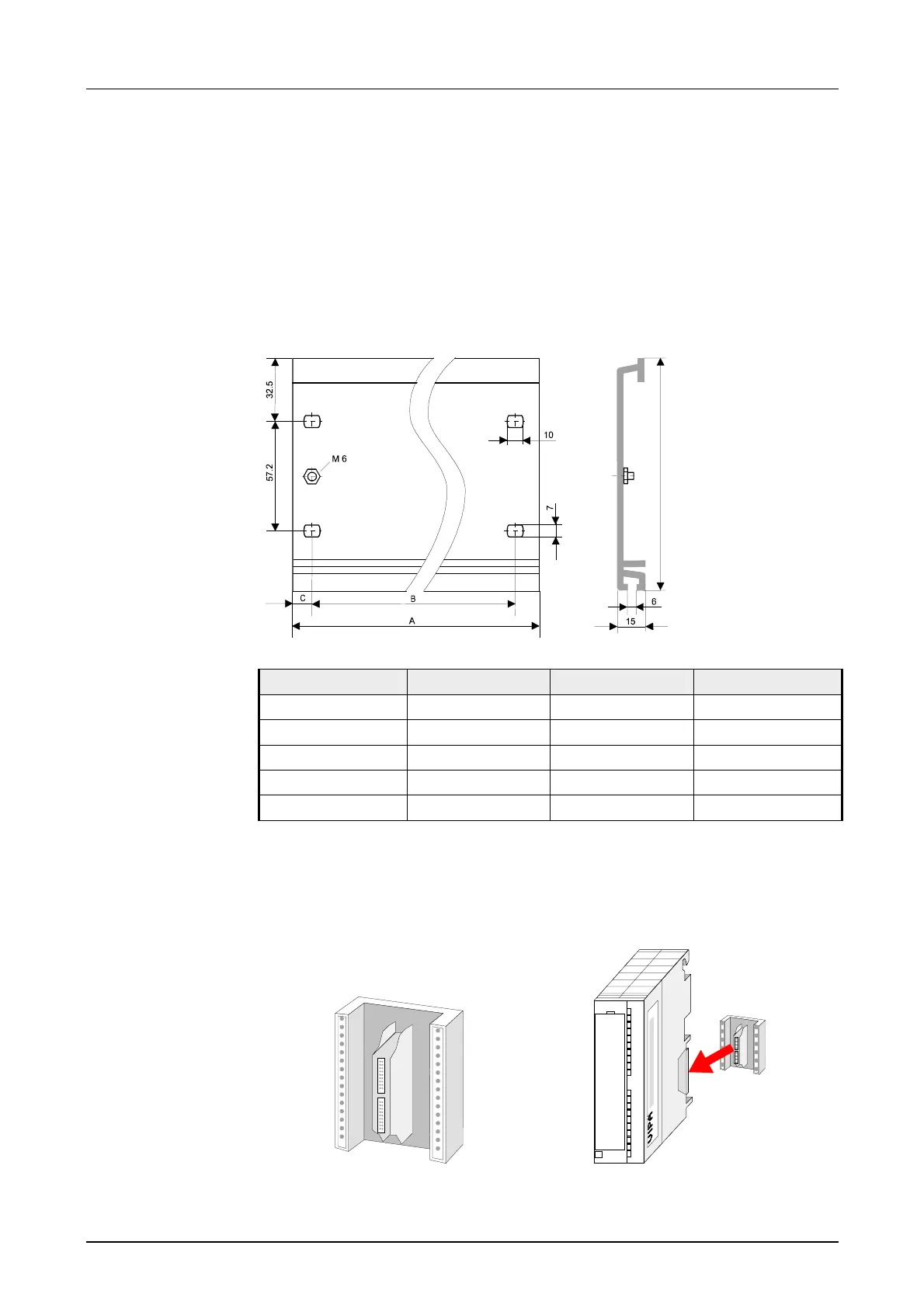
The single modules are directly installed on a profile rail and connected via
the backplane bus connector. Before installing the modules you have to
clip the backplane bus connector to the module from the backside.
The backplane bus connector is delivered together with the peripheral
modules.
G
122
Order number A B C
VIPA 390-1AB60 160mm 140mm 10mm
VIPA 390-1AE80 482mm 466mm 8.3mm
VIPA 390-1AF30 530mm 500mm 15mm
VIPA 390-1AJ30 830mm 800mm 15mm
VIPA 390-9BC00* 2000mm
Drillings only left
15mm
* Unit pack: 10 pieces
For the communication between the modules the System 300 uses a
backplane bus connector. Backplane bus connectors are included in the
delivering of the peripheral modules and are clipped at the module from the
backside before installing it to the profile rail.
General
Profile rail
Bus connector

 Loading...


