Manual VIPA System 300S SPEED7 Chapter 5 Deployment I/O periphery
HB140E - CPU SC - RE_313-6CF03 - Rev. 07/45 5-7
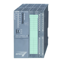
CPU 313SC/DPM: Pin assignment and status indicator
Pin
21
22
23
24
25
26
27
28
29
30
31
32
33
34
35
36
37
38
39
40
Assignment
Power supply +DC 24V
Q+0.0 / Channel 0 Output
Q+0.1 / Channel 1 Output
Q+0.2 / Channel 2 Output
Q+0.3 / Channel 3 Output
Q+0.4
Q+0.5
Q+0.6
Q+0.7
Ground DO
Power supply +DC 24V
Q+1.0
Q+1.1
Q+1.2
Q+1.3
Q+1.4
Q+1.5
Q+1.6
Q+1.7
Ground DO
Connection
=
2L+
2M
31
32
33
34
35
36
37
38
39
40
=
3L+
3M
22
21
23
24
25
26
27
28
29
30
DO
LEDs
.0
.1
.2
.3
.4
.5
.6
.7
F
.0
.1
.2
.3
.4
.5
.6
.7
F
+0
+1
DI
DO
+1
+0
1L+2L+
3L+
DI 16x
DC24V
DO16 x
DC24V
0,5A
DI
DO
.0 ... .
2L+
F
.0 ... .
3L+
F
DO:
L2+, L3+
0 ... .7
F
LED (green)
Supply voltage
available for
DO
LEDs (green)
Q+0.0 to
Q+0.7
resp. Q+1.0 to
Q+1.7
on at active
output
LED (red)
Overload or
short circuit
error
The CPU 313SC/DPM creates in its peripheral area an area for input
respectively output data. Without a hardware configuration the in the
following specified default addresses are used.
Sub module Default
address
Access Assignment
DI16/DO16 124 Byte Digital Input I+0.0 ... I+0.7
125 Byte Digital Input I+1.0 ... I+1.7
Count 768 DInt Channel 0: Count value / Frequency value
772 DInt Channel 1: Count value / Frequency value
776 DInt Channel 2: Count value / Frequency value
780 DInt reserved
Sub module Default
address
Access Assignment
DI16/DO16 124 Byte Digital Output Q+0.0 ... Q+0.7
125 Byte Digital Output Q+1.0 ... Q+1.7
Count 768 DWord reserved
772 DWord reserved
776 DWord reserved
780 DWord reserved
Access to the
digital part
Input range
Output range

 Loading...