Installation and Connections (System Examples)
• For 4K streaming, the total number of streams (800xn) must be ≤ 10,000.
• For 1080p streaming, the total number of streams (200xn) must be ≤ 10,000.
INSTALLATION AND CONNECTIONS (SYSTEM EXAMPLES)
This section provides installation and connection instructions for five configuration examples. For each encoder and decoder in the
system examples below, follow these step-by-step connection instructions.
1. Use an HDMI cable to connect the AV source to the HDMI Input port on the encoder unit.
2. (Optional) Use a second HDMI cable to connect the HDMI Loop-through port on the encoder unit to a local display.
3. Connect an HDMI cable from the display to the HDMI Output port on the decoder unit.
4. Connect a CAT 5 (or better) cable from the Ethernet port on the encoder unit to a PoE port on the network switch.
5. Connect a CAT 5 (or better) cable from the Ethernet port on the decoder unit to a PoE port on the network switch.
6. (Optional) Connect the included 5V DC power supplies to both the encoder and decoder units. Connect the included AC power
cords from the power supplies to available electrical outlets.
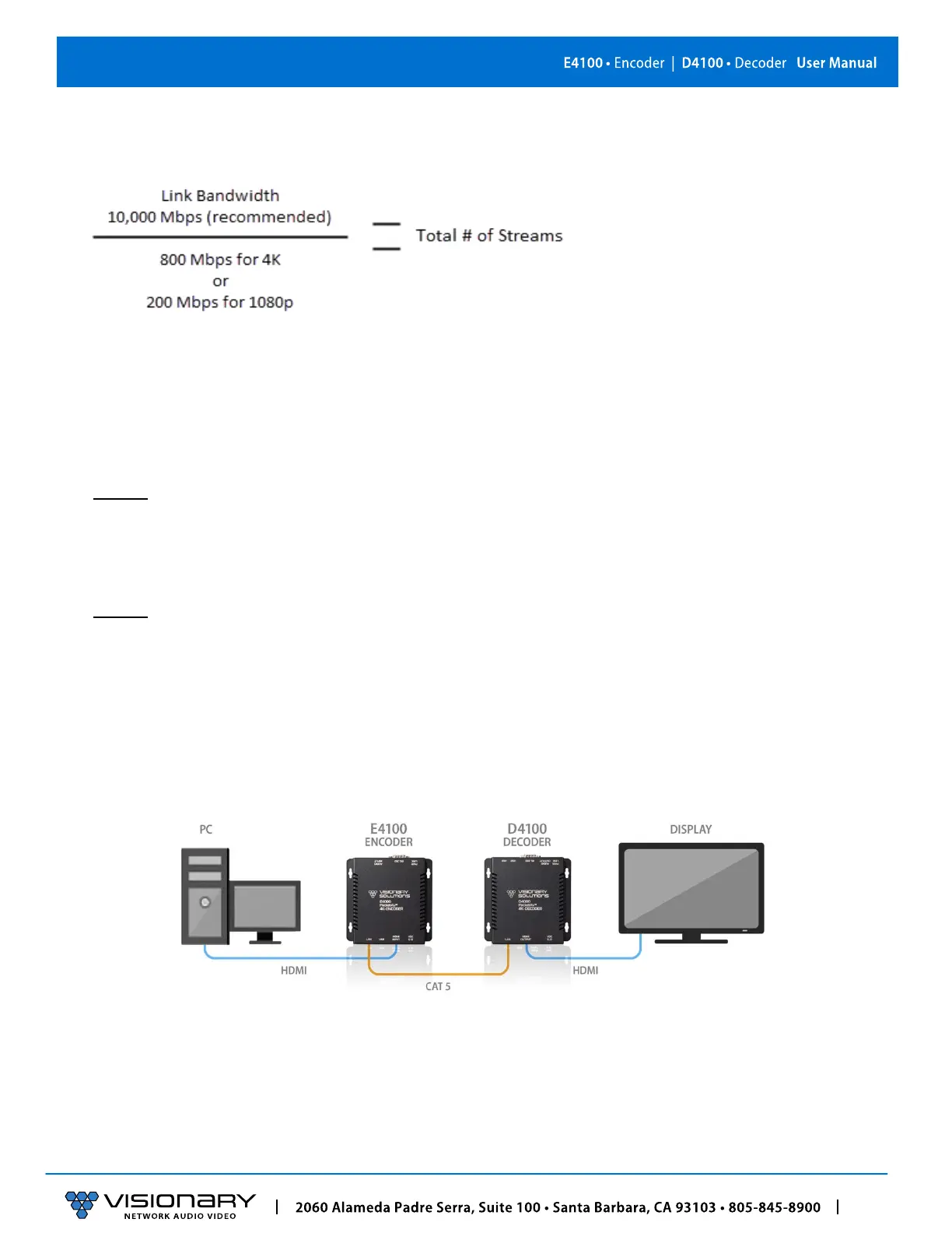
ONE SOURCE TO ONE DISPLAY
In this basic installation scenario, sending video from a single source to a single display, a single encoder and decoder (point-to-
point) can be linked directly together or over a network. If linked directly, the CAT 5e (or better) cable linking the devices should not
run more than 100m (328ft).
The devices do not connect automatically and must first be configured through embedded web interfaces. This step requires a
connection to a network. Once the devices are linked on the network, they can be connected directly. See section Configuration.
Figure 3. One Source to One Display Diagram