EasyManuals Logo

Vislink UltraReceiver LD User Manual

Vislink UltraReceiver LD
38 pages
To Next Page IconTo Next Page
To Previous Page IconTo Previous Page
Page #12 background imageLoading...
Page #12 background image
UltraReceiver LD User Manual
Introduction
Issue No: 2.01 Page: 6
Ref: ULRXLD-ASUM-700X Copyright © 2020 Vislink Technologies, Inc.
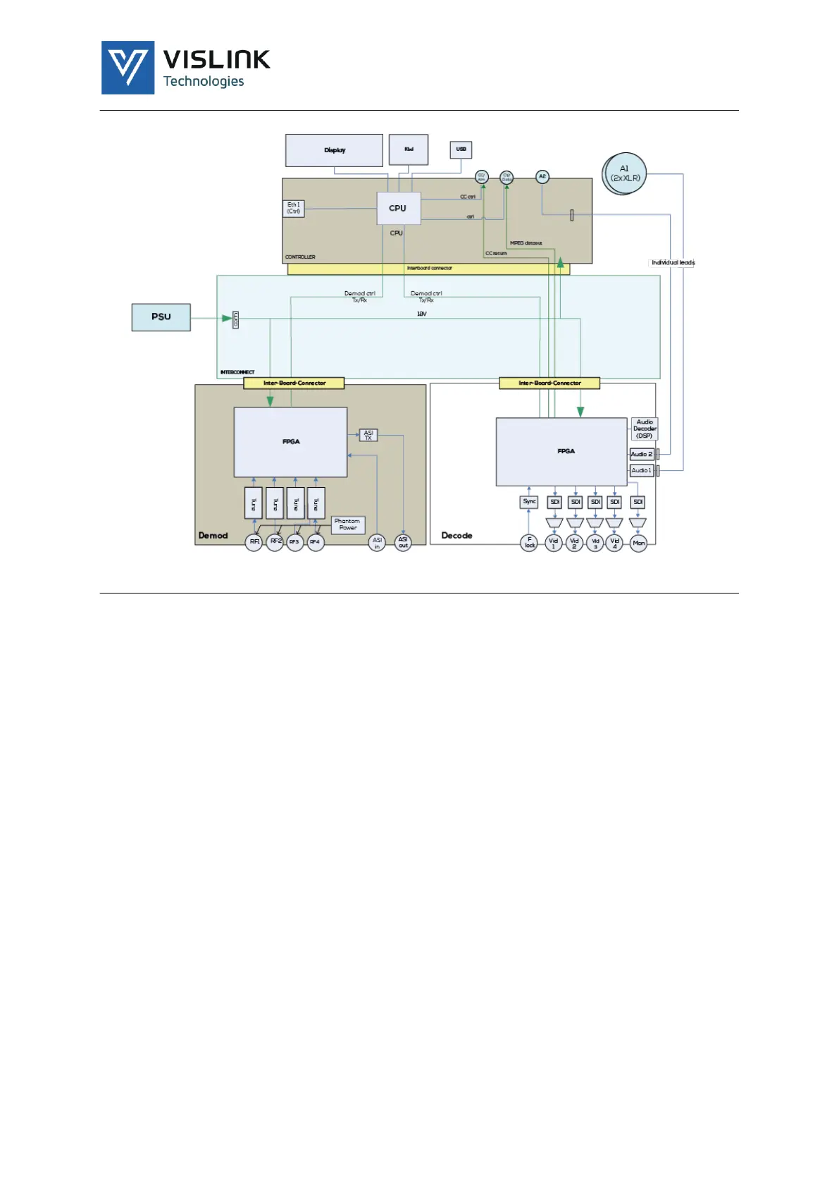
Figure 2-1 Internal Architecture Overview
Figure 2-1 shows how the Demodulator board generates an ASI stream from the
RF inputs and/or the external ASI. The ASI Stream routes to the Decoder board to
generate the Video and Audio outputs. The Decoder also extracts embedded (or
’wayside’) RS232 data (if present in the transmission). It also handles return data
to a VISLINK Camera Control System, such as FocalPoint.

Table of Contents

Questions and Answers:

Question and Answer IconNeed help?

Do you have a question about the Vislink UltraReceiver LD and is the answer not in the manual?

Vislink UltraReceiver LD Specifications

General IconGeneral
BrandVislink
ModelUltraReceiver LD
CategoryReceiver
LanguageEnglish

Related product manuals