Page.62.
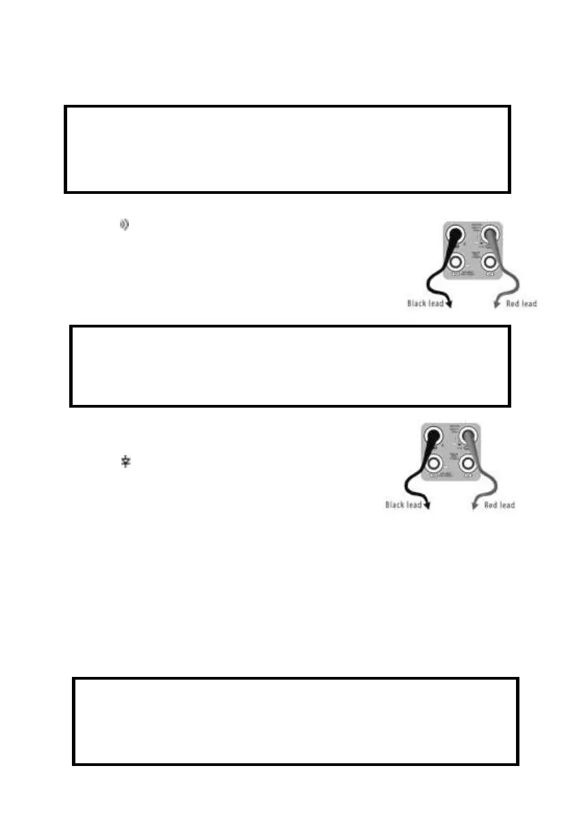
a. Connect the black test lead to the “COM” jack and the red test lead to the “V/Ω” jack.
b.to select , enter the continuity test, Connect test leads across
two point of the circuit under testing.
c. If continuity exists (i.e., resistance less than about 50Ω), built-in
buzzer will sound.
G. Diode Testing
a. Connect the black test lead to the “COM” jack and the red test
lead to the “V/Ω” jack. (the red lead anode “+” )
b. to select , enter the diode testing.
c. Connect test red lead across to the anode, the black lead to the
cathode of the diode under testing.
d. Connect test red lead across to the cathode, the black lead to the anode of the diode under
testing.
e .Tested diode, forward voltage low 30mv,there is sound indication ,then can finish the testing
quickly without view the screen.
H. Capacitance Measuring
WARNING!
When testing the circuit continuity, be sure that the power of the circuit has been shut down and all
capacitors have been discharged fully.
WARNING!
The capacitance of a capacitor should be tested separately, should not test in the installation
of circuit.
WARNING!
To avoid electric shock, be sure the capacitors have been discharged fully before measuring the
capacitance of a capacitor.