13
2. Turnonthemainwatervalveinthehouse.
3. Fullyopenacoldwaterfaucet-preferablyalaundrysinkorbathtubwithnoaerator.
4. Thisallowstheremovalofanydebrisfrompipingwhichmayhaveoccurredduringinstallation.Checkforleaks.
5. Turnoffthemainwatervalveinthehouse.Keepthelaundrysinkfaucetorbathtubfaucetwithnoaeratoropen.
6. Thesystemisnowreadyforfillingtheresintankwithwater.Forthepurposeoffillingthesoftenerresintankthebypass
assemblypistonrodhastobepushedtothe“InService”position.TurnonthemainwaterlineSLOWLYtoexpelairinthe
resintankandfilltheresintankwithwater.Checkforanyleaksatallconnectionpoints.Whenthelaundrysinkorbathtub
faucetisoniteliminatesanyairbubblesintheresintank.Notethecolourofthewatercomingfromthefaucetorlaundrytub
faucet.Ifdiscolouredletwaterrununtilclear.
NOTE: At no time should there be “large particles” of media noticed at a faucet which you opened. If this is seen immediately
shut off the water and bypass assembly as this could be an indication of a distributor failure. Contact manufacturer or
distributor for assistance.
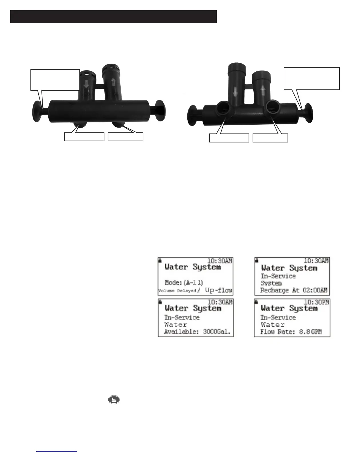
7. Whenthebypassassemblyisinservicemode
andthedisplayscreenshowsthefollowing
every5seconds:
i) Mode(A-11)VolumeDelayed/Up
Flow.Theregenerationisbyupflow.
RegenerationwillbeginwhenSoft
watercapacity(VolumeU.S.
Gallons)isdepletedandtime
reachestheregenerationtime.
ii) In-serviceregenerationtime
iii) In-servicesoftwateravailable
iv) In-serviceflowrate
8. Add2.6U.S.Gallonsofwatertothebrinetankduringinitialstart-uponly.Thiswillallowforthefirstregenerationbrine
solution.Afterthefirstregenerationthebrinetankrefillsautomaticallyforfutureregenerations.
NOTE: If too much water is put into the brine tank during softener start- up it could result in salty water complaint after the
first regeneration. During the first regeneration the unit will draw out the initial volume of brine solution and refill it with
the correct volume of water in the brine tank for the next regeneration.
9. Pressthemanual/returnkey tostartthemanualregenerationcycletocheckforleaks.
1. After installation is completed, push the piston plunger on the bypass assembly to bypass mode.
The head of the piston plunger is identified with a red circle.
sTarT-up insTruCTions
Bypass assembly with inlet ports downward Bypass assembly with inlet ports upward
Plunger in
bypass mode
Plunger in
bypass mode
Outlet Port
Outlet Port
Inlet Port
Inlet Port