4
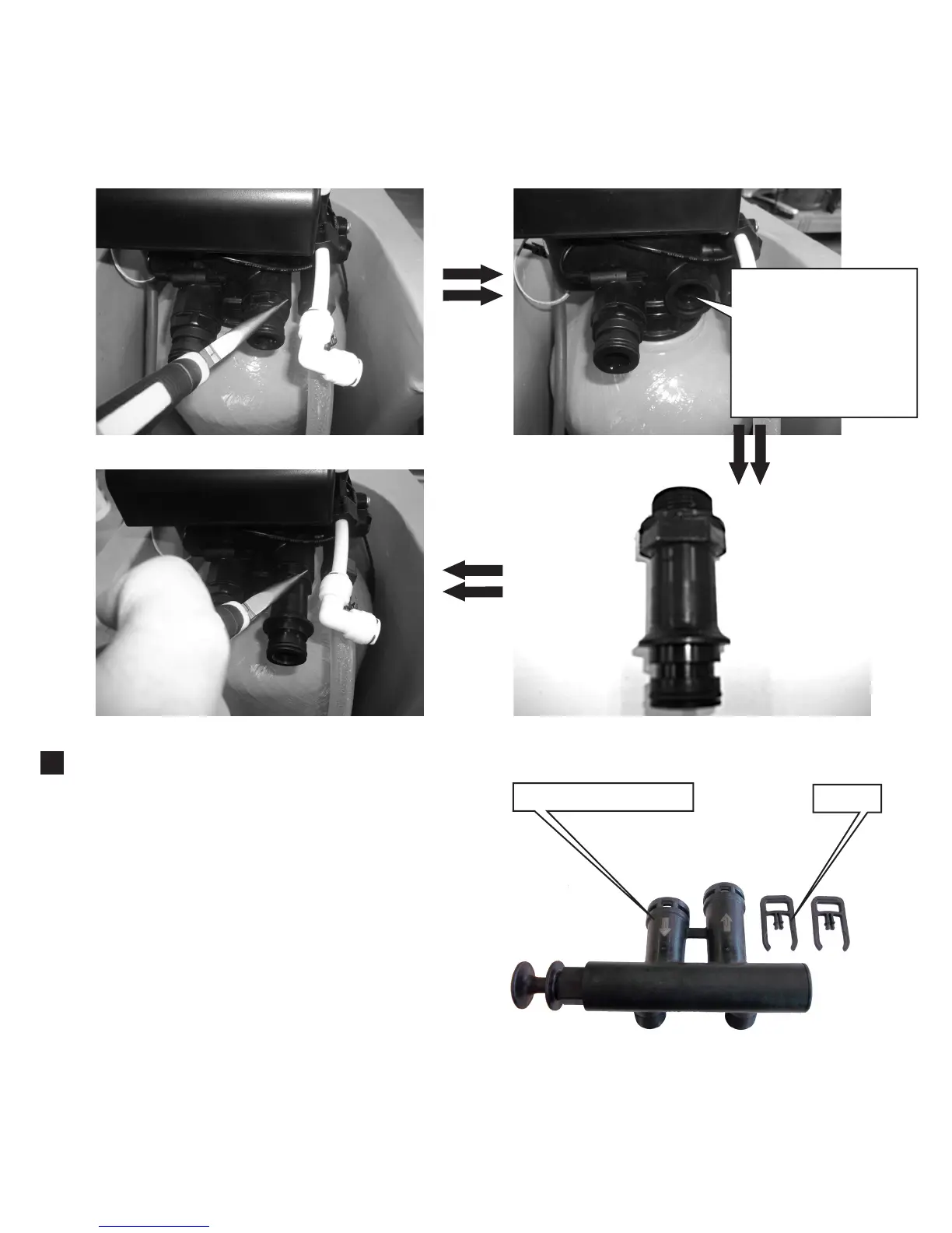
Toremovetheshortinletadapteruseneedlenosepliers.Theadapterunscrewscounterclockwise
(Fig.E).Thereisagasketinsidetheinletvalveport(FigF).Pleasedonotremovetheblackgasketwhen
removingtheshortadapterandreplacingitwiththelongeradapter(Fig.G).Tightenthelongeradapter
clockwisewithneedlenosepliers(Fig.H).
The bypass assembly is typically used to isolate
thecontrolvalvefromtheplumbingsystem’swater
pressureinordertoperformcontrolvalverepairs
or maintenance. The ¾” full flow bypass valve
incorporates a service flow and bypass position.
The bypass assembly uses a piston type plunger
design to movefrom bypass to service flow. The
bypasspositionisusedtoturnoffwaterflowtothe
valve. The in service flow position delivers water
to the valve and tank to be softened and then
deliverssoftwaterthroughthewaterplumbingin
thebuilding.
Besuretoinstallthebypassassemblyontothemain
controlvalve,beforebeginningplumbingormake
provisionsintheplumbingsystemforabypass.
Theviewofthebypassassembly(FIG.I)listsallthe
components.
Fig. E - Short Inlet Adapter
Fig. H - Long Adapter installed
Fig. F - Short Adapter Removed
Fig. G - Long Adapter
CAUTION:Gasket
isininletvalveport.
Donotremovegasket
fromvalveportwhen
removingtheshort
inletadapter.
Bypass Assembly
Clips
2.
Fig. I