7
2. Bypass Assembly Connection: Install the bypass valve onto the main control
valve using the H clips before beginning plumbing. (See Fig. N or O)
3. Theinstallationofthewatersoftenermustbecarriedoutinaccordancewithstate,localandprovincial
plumbingcodes.
4. Thecontrolvalve,fittingsandbypassassemblyaredesignedtoaccommodateminorplumbing
misalignments.Thereisasmallamountof“give”toproperlyconnectthepipingbutthewatersoftener
isnotdesignedtosupporttheweightoftheplumbing.
DonotuseVaselineoils,otherhydrocarbonlubricantsorspraysiliconeanywhere.Afoodgrade
siliconelubricantmaybeusedonlyonO-rings.
5. Donotusepipedopeorothersealantsonthreads.Teflontapeshouldbeusedonthethreadsofthe¾”
inletandoutletportsonthebypassassembly.Fittingstoconnect¾”or½”copperpipeor¾”or
½”pexpipetothebypassassemblyarenotsupplied.
6. Thediagramsbelowshowawellinstallationandmunicipalinstallation.
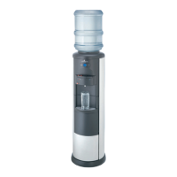
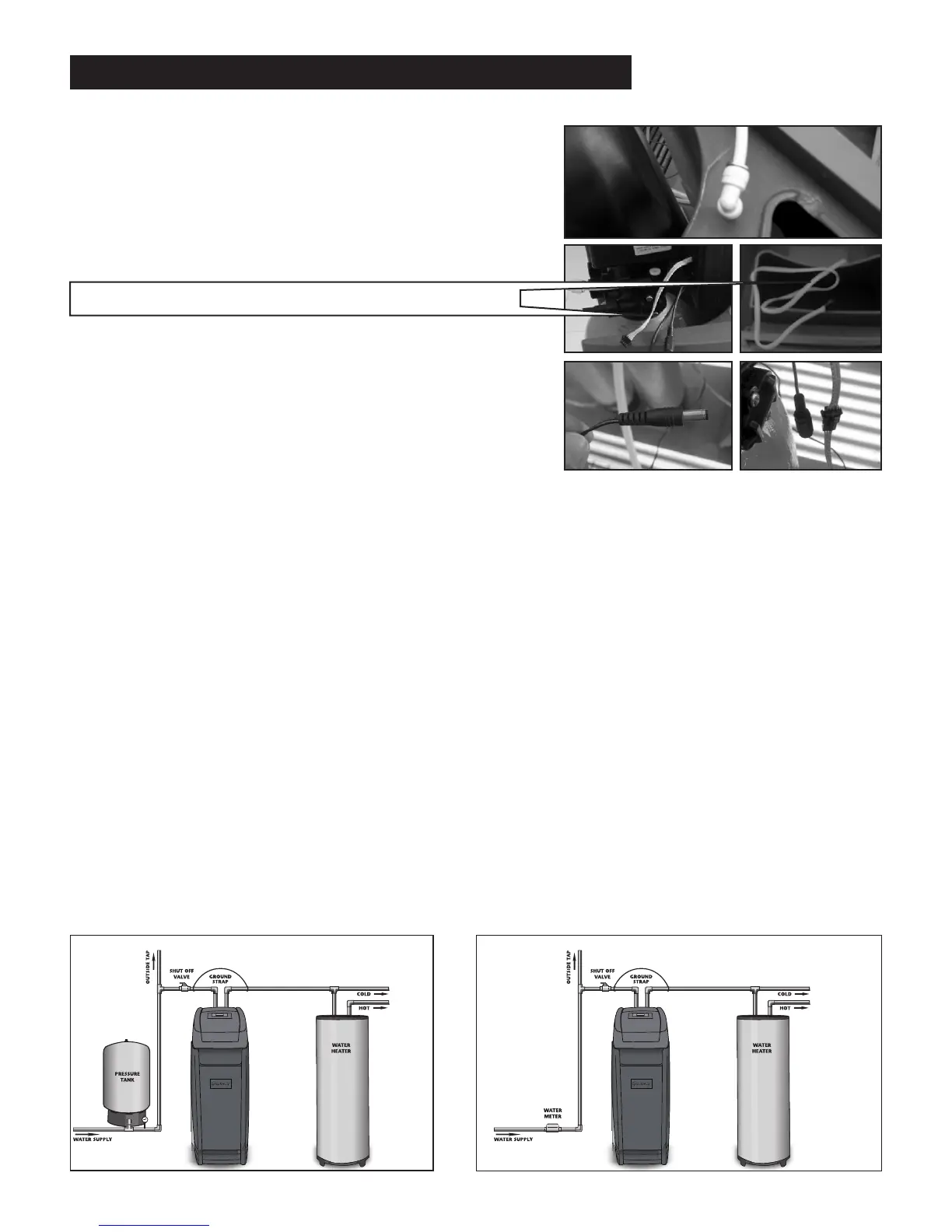
Thepoweradaptercord(Fig4.)shouldbeconnectedtothe
valvecablepowerconnector(Fig5.)shownontheright:
Water TechnologiesWater Technologies
Municipal Water InstallationWell Water Installation
Fig1.
Fig2.
Fig4.
Fig3.
Fig5.
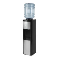
LCD display connector (connect to top cover)
insTallaTion insTruCTions (ConTinued)
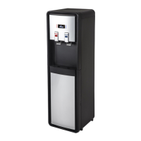
1.Placethecabinetaroundthetankandvalveheadassembly
andconnectthewhite3/8”tubingtothebrinetankusing
the quick connect as shown in Fig 1. Then LCD display
connector from valve should be connectedtoLCD display
connectorfromthecoverasshowninFig2&3.