VITRIKO
Mobile Data Experts
5. R O U T E R DESIGN
5.6 Mechanical dimensions and mounting recommendations
Mounting rec o mm e nd a ti o ns :
• possibility to be put on a w o r k surface,
• DIN rail with clips CKD2 (ELPAC clip SL for metal v e r s i o n ) are included.
F o r the most of applications with a built-in router in a switch board it is possible to r e co g ni z e
two kinds of environments:
• no public and industry environment of low v o l t a g e with high interference,
• public environment of low v o l t a g e without high interference.
F o r both of these environments it is possible to mount router to a switch board, the following
there is no need to have e x a m i n a t i o n immunity or issues in connection with EMC according t o
EN 60439-1 ed.2:00 + A1:04.
F o r compliance of EN 60439-1 ed.2:00 + A1:04 specification it is necessary t o observe next
assembly of the router to the switch – board:
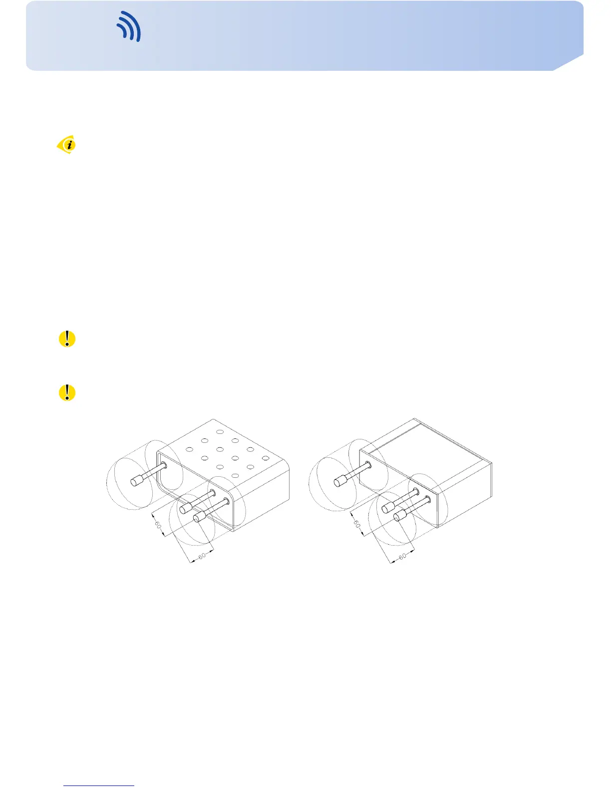
• for whip antennas w e r e co m me n d to observe a distance of 6 cm from cables and metal
surfaces on e v e r y side according to the next picture due to the elimination of interfer-
ence, while using an e x t e r n a l antenna e x c e p t for the switch-board it is necessary to fit a
lightening conductor,
• before mounting a router on sheet-steel w e rec o mm e nd using an e x t e r n a l antenna,
Figure 12: Space around antennas Figure 13: Space around antennas fo r SL
9
Contact www.vitriko.com info@vitriko.com