VITRIKO
Mobile Data Experts
5. R O U T E R DESIGN
5.8.2 P o w e r connector PWR
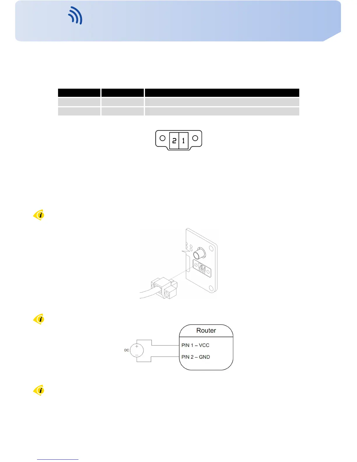
P a n e l soc ket 2-pin.
Pin number Signal mark Description
1 V C C ( + ) P o s i t i v e pole of DC supply v o l t a g e (+10 to +30 V DC)
2 GND(-) Negative pole of DC supply v o l t a g e
T a b l e 7: Connection of power connector
Figure 21: P o w e r connector
P o w e r supply fo r router is r e qu i red between +10 V to +30 V DC supply. Protection against
reve rs e d polarity without signaling is built into the router.
The power consumption during rece i vi ng is 2,3 W . The peak power consumption during
data sending is 5,5 W . However, v a l u e s of consumption can be increased, if some e x p a n s i o n
port is eqquipped. F o r correct operation it is necessary that the power source is able to supply
a peak current of 1 A.
Connector on the power cable connects into the power connector on the router head and
tightens locking screws (see figure below).
Figure 22: Connection of power supply connector
Circuit e x a m p l e :
Figure 23: Connection of power supply
The positive pole V C C is marked b y a r e d socket on the power.
14
Contact www.vitriko.com info@vitriko.com