VITRIKO
Mobile Data Experts
5. R O U T E R DESIGN
The user interface I/O is for processing of binary input signal and t o control (settings) of
binary output signal. Binary output is not switched to ground in the default configuration.
Maximum load binary output is 30 V / 100 mA. The constant current supplied b y the binary
input is 3 mA.
Connector I/O cable connect into the I/O connector on the router head and tighten locking
screws (see figure below).
Figure 36: Connection of I/O cable
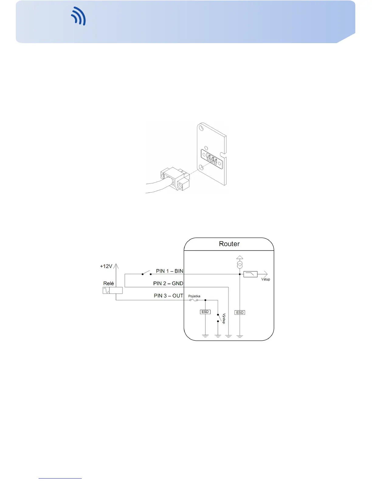
Circuit e x a m p l e of a binary input or output equipment with router:
Figure 37: Connection of input and output to the router
21
Contact www.vitriko.com info@vitriko.com