VITRIKO
Mobile Data Experts
5. R O U T E R DESIGN
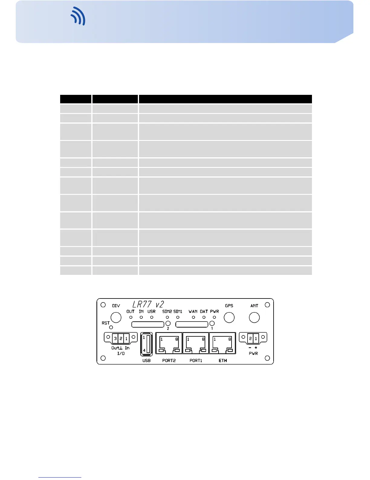
5.8 Description of the front panel
On the front panel is located:
Caption Connector Description
PWR 2-pin Connector for the power supply adapter.
ETH RJ45 Connector for connection into the local computer network.
PORT1 RJ45 Connector for e x p a n s i o n port RS232, RS458/422, MBUS,
ETHERNET, CNT or S W I T C H .
PORT2 RJ45 Connector for e x p a n s i o n port RS232, RS485/422, MBUS,
S W I T C H , WIFI, WMBUS or SDH (only FULL v e r s i o n ) .
ANT SMA Connector for main antenna.
DIV SMA Connector for diversity antenna.
GPS SMA Connector for GPS antenna. It can be r e pl a ce d with connec-
tor for WIFI or WMBUS antenna.
WIFI R - S M A Connector for WIFI antenna. Only when router is equipped
with an e x p a n s i o n port WIFI.
WMBUS SMA Connector for WMBUS antenna. Only when it is equipped
with an e x p a n s i o n port WMBUS.
USB USB-A Host Connector for connection of USB devices t o the router. Sup-
ports devices with PL-2303 and FTDI USB/RS232 converters.
I/O 3-pin Connector for connection of the binary input and output.
SIM1 — Holder for the first SIM card.
SIM2 — Holder for the second SIM card (only FULL v e r s i o n ) .
T a b l e 5: F r o n t panel description
Figure 20: F r o n t panel LR77 v2F SL
12
Contact www.vitriko.com info@vitriko.com