VITRIKO
Mobile Data Experts
5. R O U T E R DESIGN
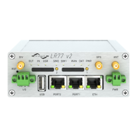
PORT2 cable plug into the RJ45 connector labeled as PORT1 (see figure below).
Figure 31: PORT2 cable connection
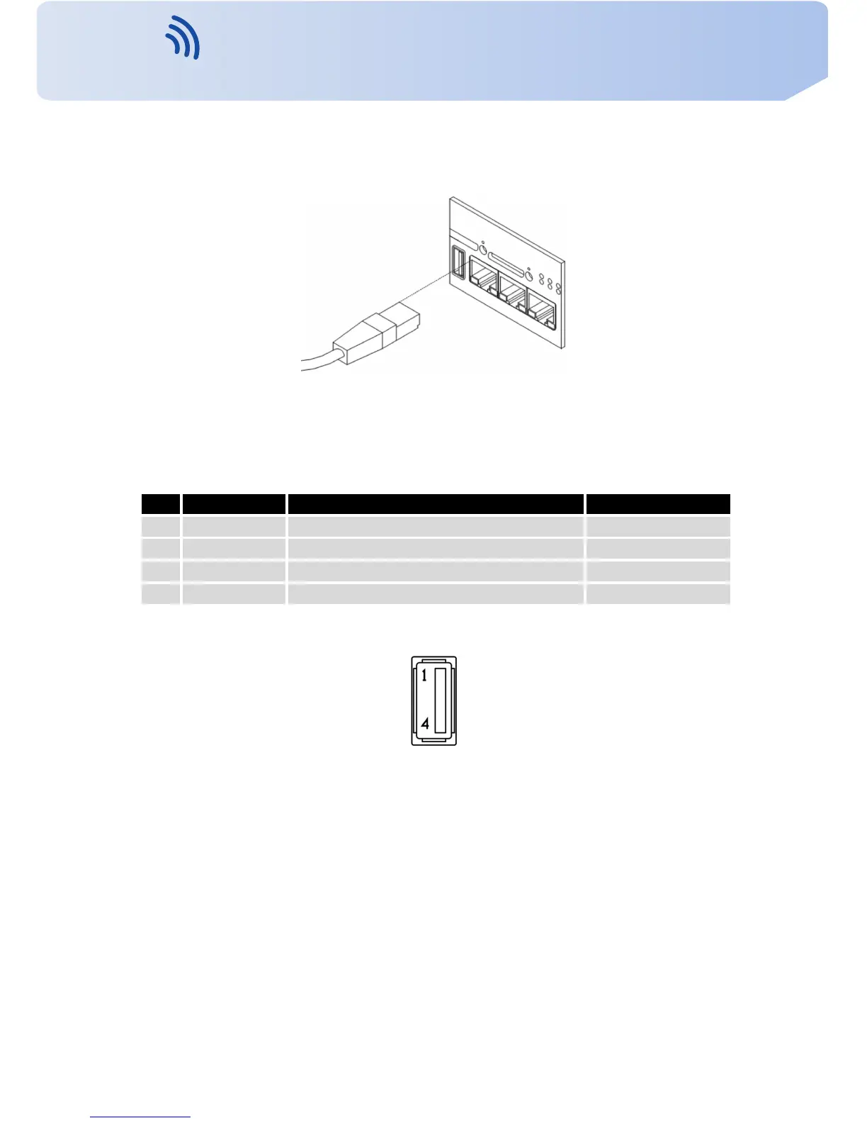
5.8.8 USB P o r t
P a n e l soc ket USB-A.
Pin Signal mark Description Data flow direction
1 +5 V P o s i t i v e pole of 5 V DC supply v o l t a g e
2 USB data - USB data signal – negative pole Input/Output
3 USB data + USB data signal – positive pole Input/Output
4 GND Negative pole of DC supply v o l t a g e
T a b l e 9: Connection of USB connector
Figure 32: USB connector
19
Contact www.vitriko.com info@vitriko.com