VITRIKO
Mobile Data Experts
5. R O U T E R DESIGN
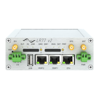
Example of connecting devices with serial interface t o the USB:
Figure 33: Connection PLC to the router
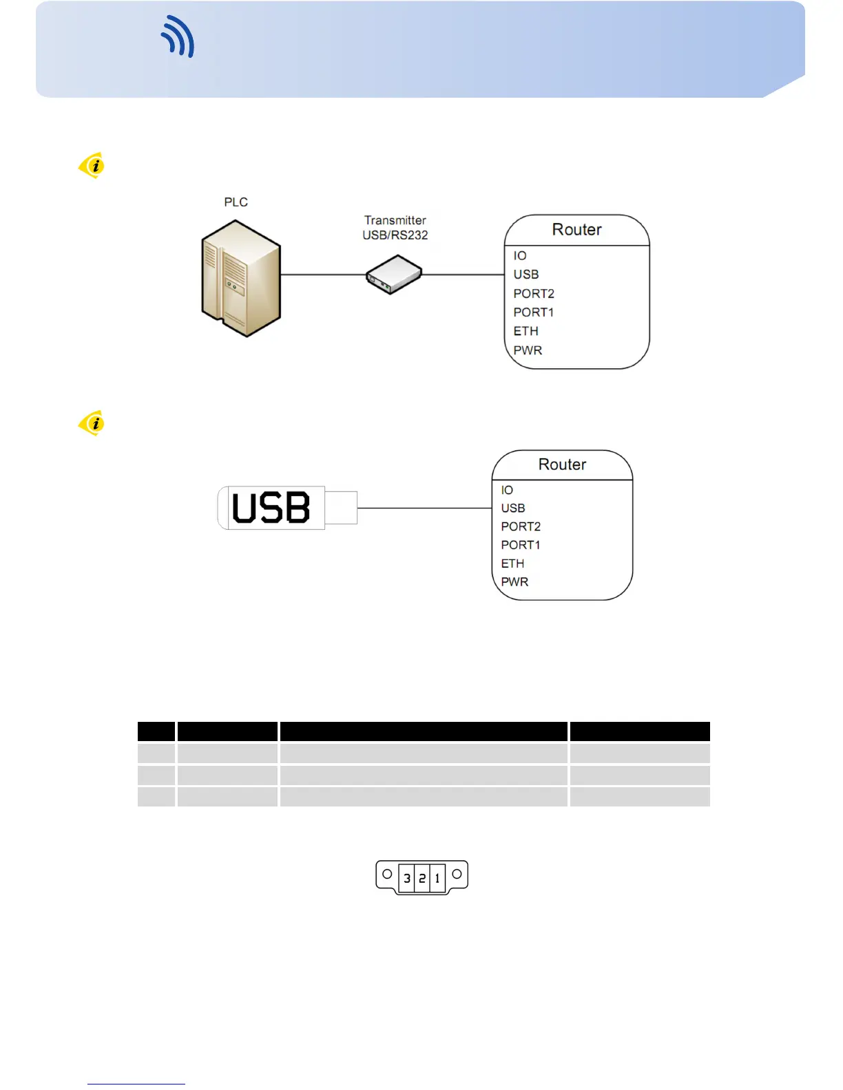
Example of connecting of USB flash disk to the USB:
Figure 34: Connection flash memory t o the router
5.8.9 I/O P o r t
P a n e l soc ket 3pin.
Pin Signal mark Description Data flow direction
1 BIN0 Binary input Input
2 GND Signálová zem
3 OUT0 Binary output Output
T a b l e 10: Connection of I/O port
Figure 35: I/O connector
20
Contact www.vitriko.com info@vitriko.comContact www.vitriko.com info@vitriko.com