19
Vivint Element Installation Guide
Wiring Diagrams
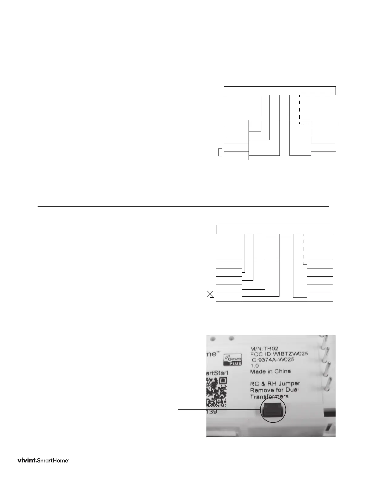
DIAGRAM 4
5 Wire Heat/Cool with separate Heating
(RH) and Cooling (RC) Transformers
1.ConnecttheWwiretotheWterminal.
Thisconnectstheheat.
2. ConnecttheYwiretotheYterminal.
Thisconnectstothecoolingcompressor.
3. RemovetheRC&RHJumper.
4. ConnecttheRHwiretotheRHterminal
andtheRCwiretotheRCterminal.This
connectspower.
5. ConnecttheGwiretotheGterminal.
Thisconnectsthefan.
6. Ifavailable,connecttheCwiretotheC
terminal.
7. Goto“ConnectYourWires”onpage11.
Y G R W C
Y2
Y
G
RC
RH
C
A
O/B
W2
W
Thermostat
Optional
C Wire
Factory
Installed
RC & RH
Jumper
Y G RC RH W C
Y2
Y
G
RC
RH
C
A
O/B
W2
W
Thermostat
Optional
C Wire
NOTE:
REMOVE
Factory
Installed
RC & RH
Jumper
DIAGRAM 3
4 Wire Heat/Cool
1. ConnecttheWwiretotheWterminal.This
connectstheheat.
2. ConnecttheYwiretotheYterminal.This
connectsthecoolingcompressor.
3. ConnecttheRHorRwiretotheRHterminal.
Thisconnectsthepower.
4. ConnecttheGwiretotheGterminal.This
connectsthefan.
5. Ifavailable,connecttheCwiretotheC
terminal.
6. Goto“ConnectYourWires”onpage11.
Remove
Jumper