21
Vivint Element Installation Guide
Wiring Diagrams
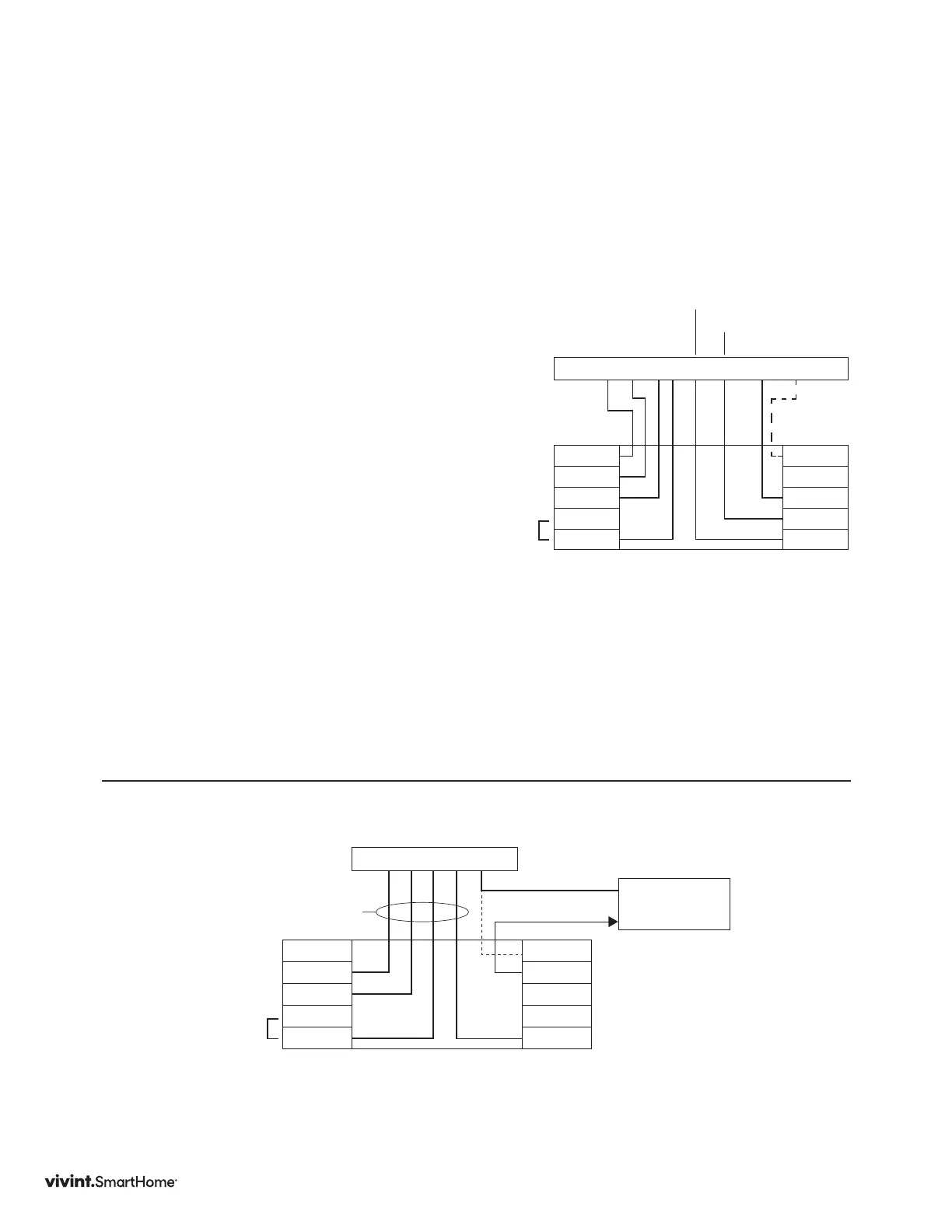
DIAGRAM 7
Two-stage Heat Pump with Two-Stage Aux Heat
TheElementcanhandleupto2stagesof
Pumpcompressionand2stagesofAUXheat.
1. ConnectOwiretotheOterminalortheB
wiretotheBterminal.Thisconnectsthe
change-overvalve.IfyouhavebothOand
B,connectonlytheOwiretotheOterminal
andDONOTconnectBtoBterminal(see
WireReferenceTableonpageXforTrane
terminallabels.).
2. ConnecttheAUX1andAUX2wirestothe
WandW2terminals.Thisconnectsthe
auxiliaryheat.
3. ConnecttheYandY2wirestotheY
andY2terminals.Thisconnectsthe
compressor.
4. ConnecttheRwiretoRHterminal.
Thisconnectsthepower.
5. ConnecttheGwiretotheGterminal.
Thisconnectsthefan.
6. Ifavailable,connecttheCwireto
theCterminal.
7. Goto“ConnectYourWires”onpage11.
Y2 Y G R W W2 O/B C
Y2
Y
G
RC
RH
C
A
O/B
W2
W
Thermostat
Optional
C Wire
Factory
Installed
RC & RH
Jumper
HVAC System
Aux Heat 2
DIAGRAM 8
Humidity/Dehumidity
YGRWC
Y2
Y
G
RC
RH
C
A
O/B
W2
W
Thermostat
The EV2 provides a 24VAC output on the A terminal when the
Humidity function is enabled and a call to humidify/dehumidify
is active. Check the units control input, an external relay may
be necessary.
24VAC Output
Optional C Wire
to thermostat
HVAC connections
as required for the
installation
Humidifier or
Dehumidifier
Common
Factory
Installed
RC & RH
Jumper