20
1.ConnecttheOwiretotheOterminal
ortheBwiretotheBterminal.This
connectsthechange-overvalve.Ifyou
havebothOandB,connectonlythe
OwiretotheOterminalandDONOT
connectBtoBterminal(seetheWire
ReferenceTableonpage23forTrane
terminallabels).
2. ConnecttheYwiretotheYterminal.
Thisconnectsthecompressor.
3. ConnecttheRwiretotheRHterminal.
Thisconnectsthepower.
4.ConnecttheGwiretotheGterminal.
Thisconnectsthefan.
5. Ifavailable,connecttheCwiretotheC
terminal.
6. Goto“ConnectYourWires”onpage11.
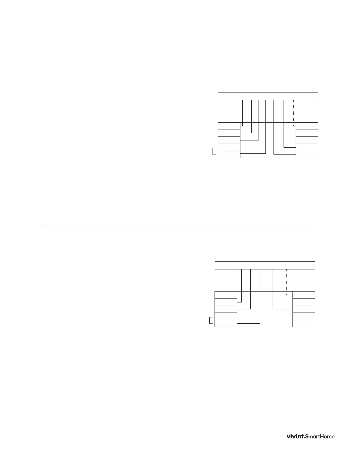
DIAGRAM 6
4 Wire Heat Pump (heat/cool) without Auxiliary Heat
Y G R O/B C
Y2
Y
G
RC
RH
C
A
O/B
W2
W
Thermostat
Optional
C Wire
Factory
Installed
RC & RH
Jumper
Y2 Y G R W W2 C
Y2
Y
G
RC
RH
C
A
O/B
W2
W
Thermostat
Optional
C Wire
Factory
Installed
RC & RH
Jumper
DIAGRAM 5
Two-stage Heat & Two-Stage Cool
TheElementcanhandleupto2stagesof
HEATand2stagesofCOOL.
1.ConnecttheWandW2wirestotheWand
W2terminals.Thisconnectsthestagesof
HEAT.
2. ConnecttheYandY2wirestotheYand
Y2terminals.Thisconnectsthestagesof
COOL.
3. ConnecttheRHorRwiretotheRH
terminal.Thisconnectsthepower.
4. ConnecttheGwiretotheGterminal.
Thisconnectsthefan.
5. Ifavailable,connecttheCwiretotheC
terminal.
6. Goto“ConnectYourWires”onpage11.
Vivint Element Installation Guide
Wiring Diagrams