44
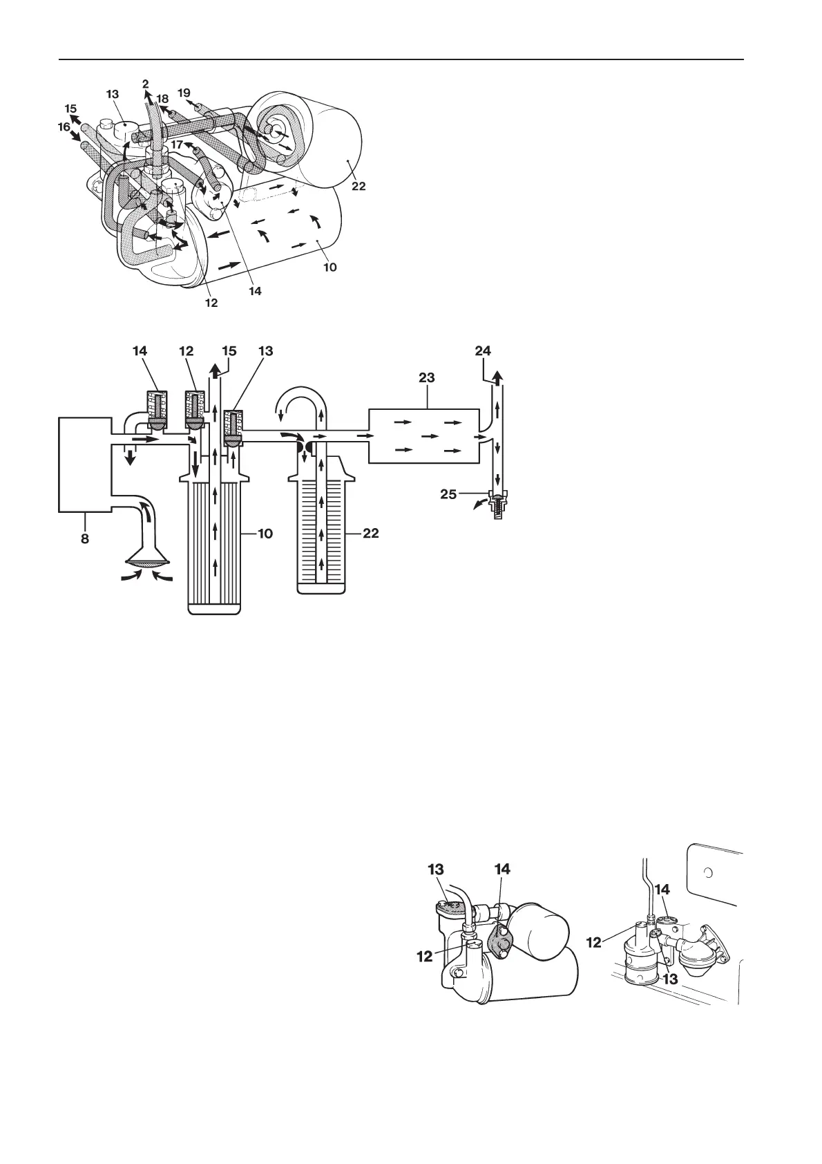
Lubrication system (partial diagram, filter housing), TAMD63
2. Pressure pipe to turbocharger 17. Return oil to oil sump via relief
10. Engine oil filter valve
12. Overflow valve 18. Pressure oil via piston cooling
13. Piston cooling valve valve to oil cooler and piston
14. Relief valve cooling
15. Filtered pressure oil to lubri- 19. Return oil to oil sump (via by-
cation system pass filter)
16. Pressure oil from oil pump 22. By-pass filter
Basic diagram, lubrication system
8. Oil pump
10. Lubricating oil filter
12. Overflow valve
13. Piston cooling valve
14. Relief valve
15. Filtered oil (pressure) to lubrication
system
22. By-pass filter
23. Oil cooler
24. Oil (pressure) to piston cooling
25. By-pass valve
*Note! By-pass filter is an accessory on
TAMD71 and TAMD72 engines.
TAMD63 TAMD71, TAMD72
Valves in the lubrication system
12. Overflow valve 14. Relief valve
13. Piston cooling valve
Valves in the lubrication system
The oil flow in the engine is controlled by four spring-
loaded valves. Three of these are located in a
mounting on the right of the engine and one at the
lower edge of the cylinder block on the left of the en-
gine.
– The relief valve (14) limits the system oil pressure
in the engine. This valve opens if the pressure is
too high and allows oil back to the oil sump at high
speeds or if the engine is cold and the lubricating
oil is more viscous.
– The overflow valve (12) opens and allows oil past
the lubricating oil filter if the resistance through the
filter is too great. This way oil can flow into the en-
gine lubrication system even if the filter is clogged.
But the oil entering the system is unfiltered. So it is
important that the filter is replaced according to the
intervals recommended in the maintenance sched-
ule.
– The piston cooling valve (13) regulates the flow of
oil through the oil cooler and on to piston cooling.
– The by-pass valve (25) permits increased oil flow
through the oil cooler. The valve opens and re-
turns excess oil not required for piston cooling
back to the oil sump.