62
TAMD72P (EDC)
The system also determines the maximum torque
available at the engine speed registered without risk-
ing damaging the engine. To protect the engine at
high engine coolant temperatures, high charge air
temperatures or excessive charge air pressure the
EDC temporarily reduces the amount of fuel (re-
duced engine output) until the current values normal-
ize.
The EDC control module also has a diagnostics sys-
tem (On-board diagnostics OBD) which assists us-
ers/service technicians to quickly determine the
cause of any malfunctions on the system using the
diagnostic lamp or a diagnostic scan tool (ST).
Electronic Diesel Control (EDC) system
(TAMD72P)
The injection pump on the TAMD72P
(“TAMD72EDC”) engine has an electronic governor.
The governor contains an electro-magnetic actuator
which effects the injection pump control rod and so
the amount of fuel injected (engine output).
The EDC system measures the charge air pressure
and charge temperature and calculates the available
air mass. This determines the amount of fuel injected
(smoke limiter function). To achieve minimal emis-
sions at start the system measures the engine cool-
ant temperature and adapts the amount of fuel re-
quired.
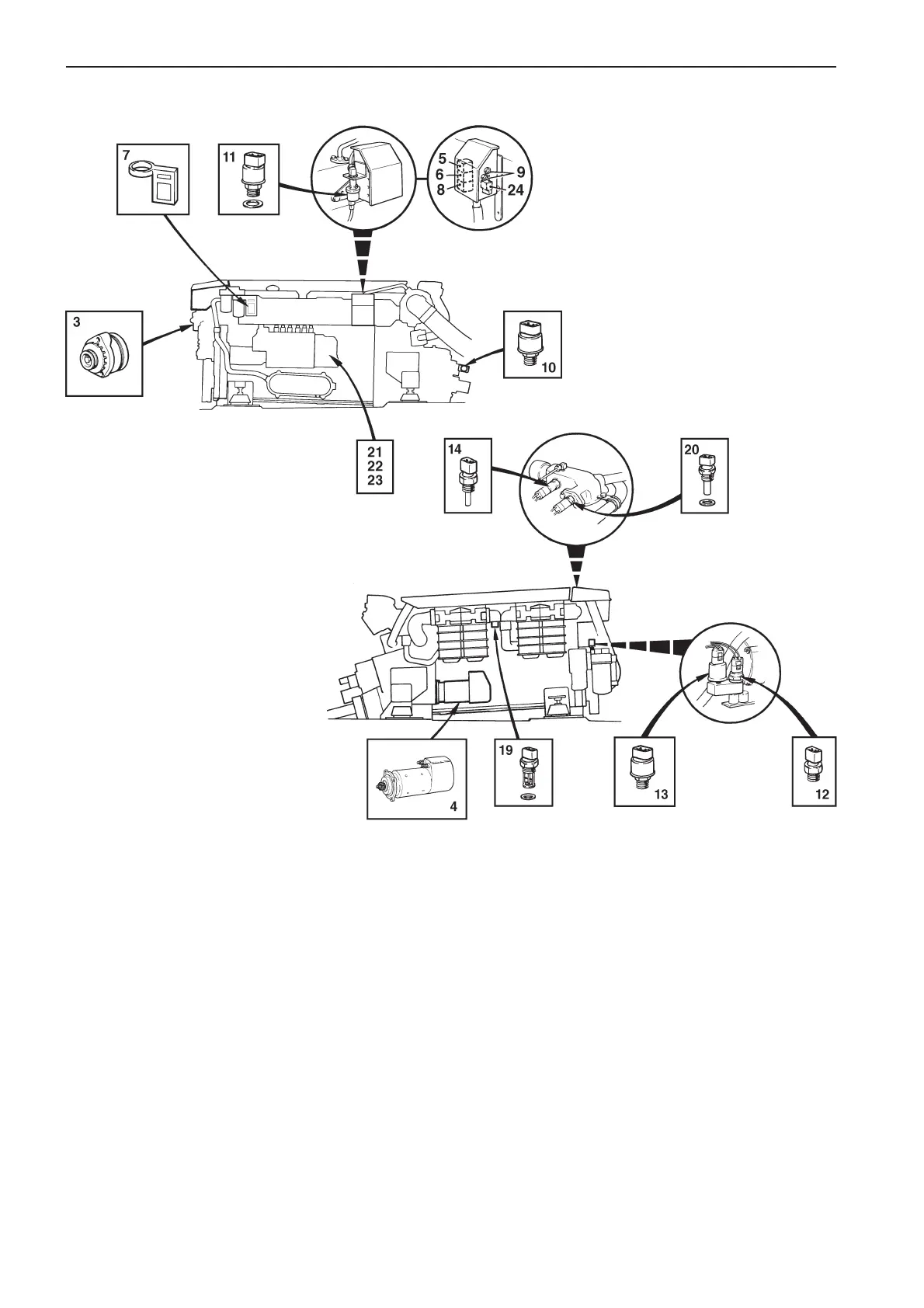
TAMD72P (EDC)
Note: The components in the figures are
numbered the same as in the engine’s wiring
diagrams on pages 79 and 81.
3. Generator (GEN)
4. Starter motor
5. Starter relay
6. Main relay
7. Electronic Diesel Control (EDC) control
module box (incl. fuel temperature sender,
EDC and turbo pressure sender, EDC)
8. Stop relay
9. Semi-automatic fuses
10. Oil pressure sender, reverse gear.
11. Pressure sender, turbo pressure, instru-
ment
12. Oil pressure switch, engine
13. Oil pressure sender, engine
14. Engine coolant temperature (ECT) sender,
instrument
19. Temperature sender, charge air, EDC
20. Engine coolant temperature (ECT) sender,
EDC
21. Position sender, control rod
22. Engine speed (RPM) sender
23. Electro-magnetic actuator, EDC
24. 2-pin connector, data link connector (DLC)