65
To simultaneously charge two independent bat-
tery circuits, fit a Volvo Penta charge distributor
to the regular generator (accessory).
2. Batteries
Always ensure that the Plus (positive) and Minus
(negative) battery leads are correctly installed on
the corresponding terminal posts on the batter-
ies. Incorrect installation can result in serious
damage to the electrical equipment. Refer to the
wiring diagrams. The battery terminal posts
should always be well cleaned and the cable ter-
minals well tightened and greased to prevent
open circuits.
Avoid booster charging the batteries. If the bat-
tery must be booster charged, first remove both
battery leads.
NOTE! Follow relevant safety regulations when
charging batteries. When charging, the cell plugs
should be unscrewed, but they should remain in
their holes. There should be good ventilation,
particularly if the batteries are being charged in a
closed area. Always turn off the charging circuit
before removing the charging connectors.
WARNING! Never allow an open flame or
electric sparks near the batteries. Never
smoke in proximity to the batteries. The
batteries give off hydrogen gas during
charging which when mixed with air can
form an explosive gas – oxyhydrogen. This
gas is easily ignited and highly volatile.
Always use protective goggles when charg-
ing and handling the batteries.
Battery electrolyte contains sulfuric acid
which is highly corrosive. Should the bat-
tery electrolyte come into contact with un-
protected skin wash off immediately using
plenty of water and soap. If battery acid
comes in contact with the eyes, immediate-
ly flush with plenty of water and obtain
medical assistance without delay.
3. See separate instructions on this page for
how to start using auxiliary batteries.
4. Connecting accessories and extra equipment
All extra equipment should be connected to a
separate junction box and fused. Extra outlets di-
rectly from the instrument panels should be
avoided. Extra outlets can be installed up to a to-
tal max. 5A (applies to all the instrument panels
as a whole).
Arc welding
Remove the positive and negative leads from the
batteries. Then remove all leads to the generator.
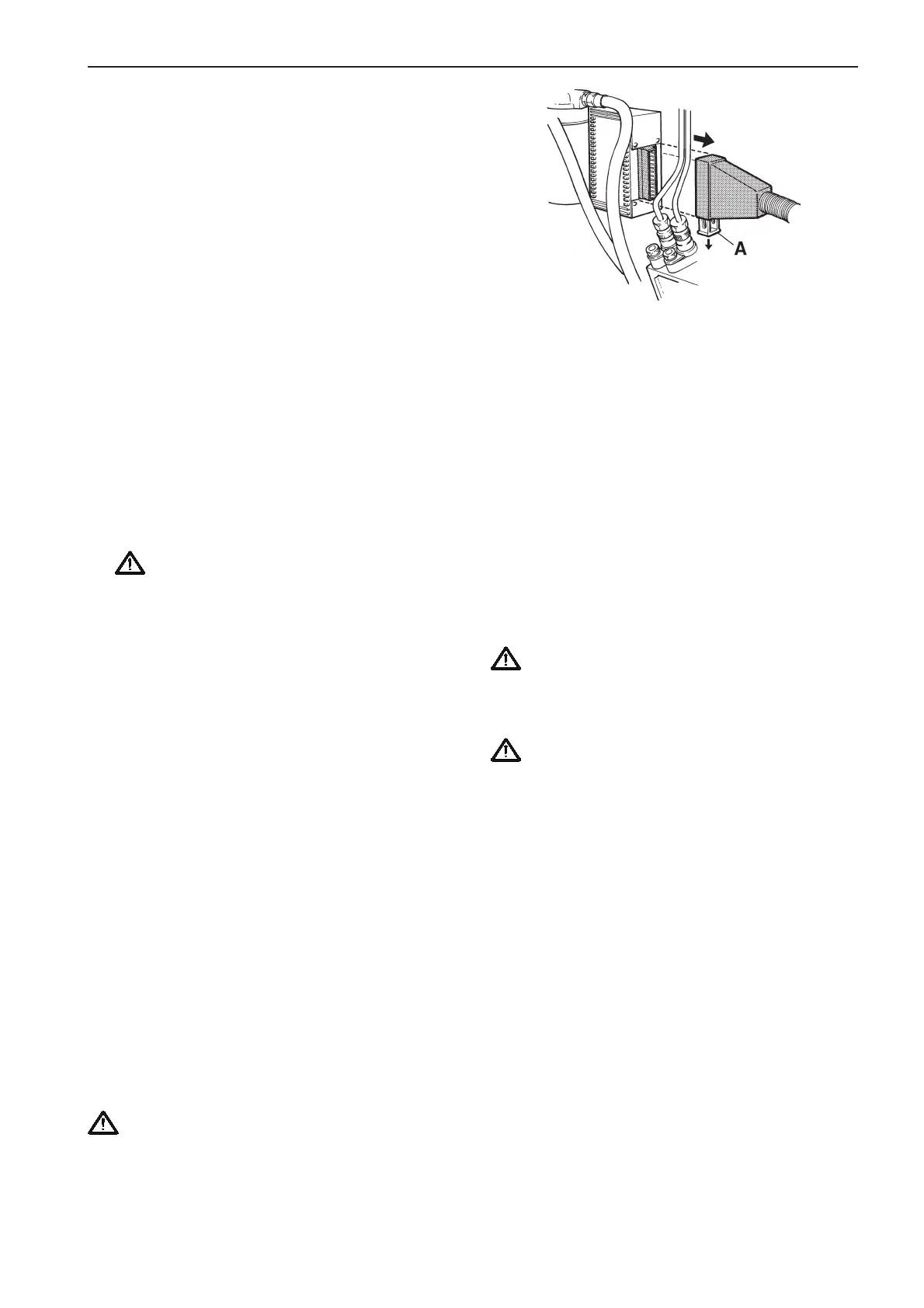
TAMD72P: Remove the connector from the EDC
system control module (located behind the fuel fil-
TAMD72P: Removing the connector from the control
module
A. Locking catch
ters). Pull down the red locking catch below the con-
nector while pulling the connector out at the same
time.
Always connect the weld clamp to the component to
be welded and as close to the welding point as pos-
sible. The clamp should never be connected to the
engine or in such a manner that the current is able to
pass over any bearings.
When welding is complete
TAMD72P: Press the connector into the EDC system
control module while pushing the locking catch up.
Always connect the leads to the generator
before replacing the battery leads.
Starting using auxiliary batteries
WARNING!
The batteries (auxiliary batteries in particular) contain
extremely explosive oxyhydrogen gas. One spark,
which may be formed if the auxiliary batteries are
connected incorrectly, is sufficient to explode a bat-
tery and cause damage and injury.
1. Check that the auxiliary batteries are connected
(in series or in parallel) so that their rated voltage
is the same as the engine’s system voltage.
2. First connect the red jump lead (+) to the auxilia-
ry battery, then to the discharged battery. Then
connect the black jump lead (–) to the auxiliary
battery, then to a spot a short distance from
the discharged batteries, for example at the
main switch on the negative cable or at the neg-
ative cable’s connection to the starter motor.
3. Start the engine. NOTE! Do not shift the con-
nections when attempting to start the engine
(spark risk) and do not lean over any of the
batteries.
4. Remove the jump leads in exactly the opposite
order to which you put them on. NOTE! The nor-
mal leads to the standard batteries should
under no circumstances be moved.