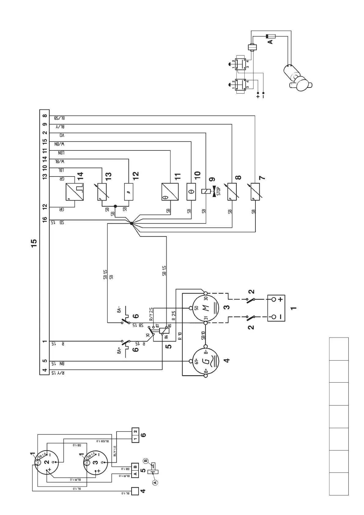
Engine
The components in the wiring diagram
have the same numbers as shown in
the key diagrams on page 60.
1. Battery
2. Main switch
3. Starter motor
4. Generator (GEN)
5. Starter relay
6. Semi-automatic fuses (8A)*
7. Oil pressure sender, reverse gear
(0 – 30 bar).
8. Turbo pressure sender (0 – 3 bar)
9. Solenoid valve (fuel shut-off
valve)
10. Coolant temperature switch
(97°C/207°F), normally open –
closes if fault occurs)
11. Coolant temperature sender (40 –
120°C/104–248°F)
12. Oil pressure switch, engine (0.7
bar, normally open – closes if
fault occurs)
13. Oil pressure sender, engine (0 –
10 bar)
14. Engine speed (RPM) sender
15. 16-pin connector
*Located in the junction box
Suggested connection of oil scav-
enging pump (draining and filling)
Cable area 1.5 mm
2
.
A. Fuse (8A/24V, or 15A/12V)
Cable areas in mm
2
are noted after the color codes in the wiring diagram.
The cable area is 0.75 mm
2
unless otherwise stated.
The cable run marked with a dashed line is not supplied by Volvo Penta
Auxiliary panel
1. Instrument lighting
2. Oil pressure gauge, reverse gear
3. Turbo charging pressure gauge
4. Connection to instr. light. on main panel
5. Connection to printed circuit card on main
panel
6. Connection to connector (18) on main panel
Cable color
BL = Blue OR = Orange
LBL = Light blue PU = Purple
BN = Brown R = Red
LBN = Light brown SB = Black
GN = Green W = White
GR = Gray Y = Yellow
Conversions mm
2
/AWG*
* American Wiring Gauge
mm
2
0.75 1.0 1.5 2.5 10 16
AWG 18 16 (17) 15 (16) 13 7 5