Cable areas in mm
2
are given following the color codes
in the wiring diagrams.
The cable area is 1.0 mm
2
unless otherwise stated.
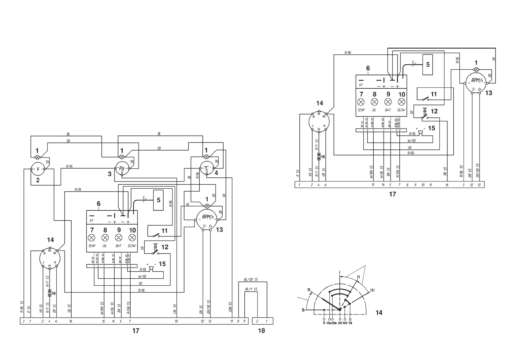
Instrument panel, (Main panel)
Spring
loaded
Spring loaded
Instrument panels
1. Instrument lighting
2. Voltmeter
3. Oil pressure gauge
4. Engine coolant temperature (ECT) gauge
5. Connector for connecting extra
warning display (accessory)
6. Control module (alarm)
7. Warning light, engine coolant temperature
(ECT)
8. Warning light, oil pressure
9. Warning lamp, charging
10. Control lamp, pre-heating
11. Instrument lighting switch
12. Alarm test/acknowledgement switch
13. Tachometer with built-in hours run meter
14. Key switch
15. Alarm
16. Connector for connecting neutral position
switch, if fitted (accessory)
17. 16-pin connector
18. 2-pin connector (for supplementary panel)
TAMD71B, TAMD72WJ-A
Up to and including engine
No. 207181083/xxxx*
*Engines fitted with a stop solenoid (applies
to the engine’s wiring diagram).
Control panel for auxiliary control position (Flying Bridge)