TAMD72P-A (12V)
Cable areas in mm
2
are noted after the color codes in the wiring diagrams.
The cable area is 1.0 mm
2
unless otherwise stated.
Conversions mm
2
/AWG
mm
2
0,5 1,0 1,5 2,5 10
AWG 20 16 (17) 15 (16) 13 7
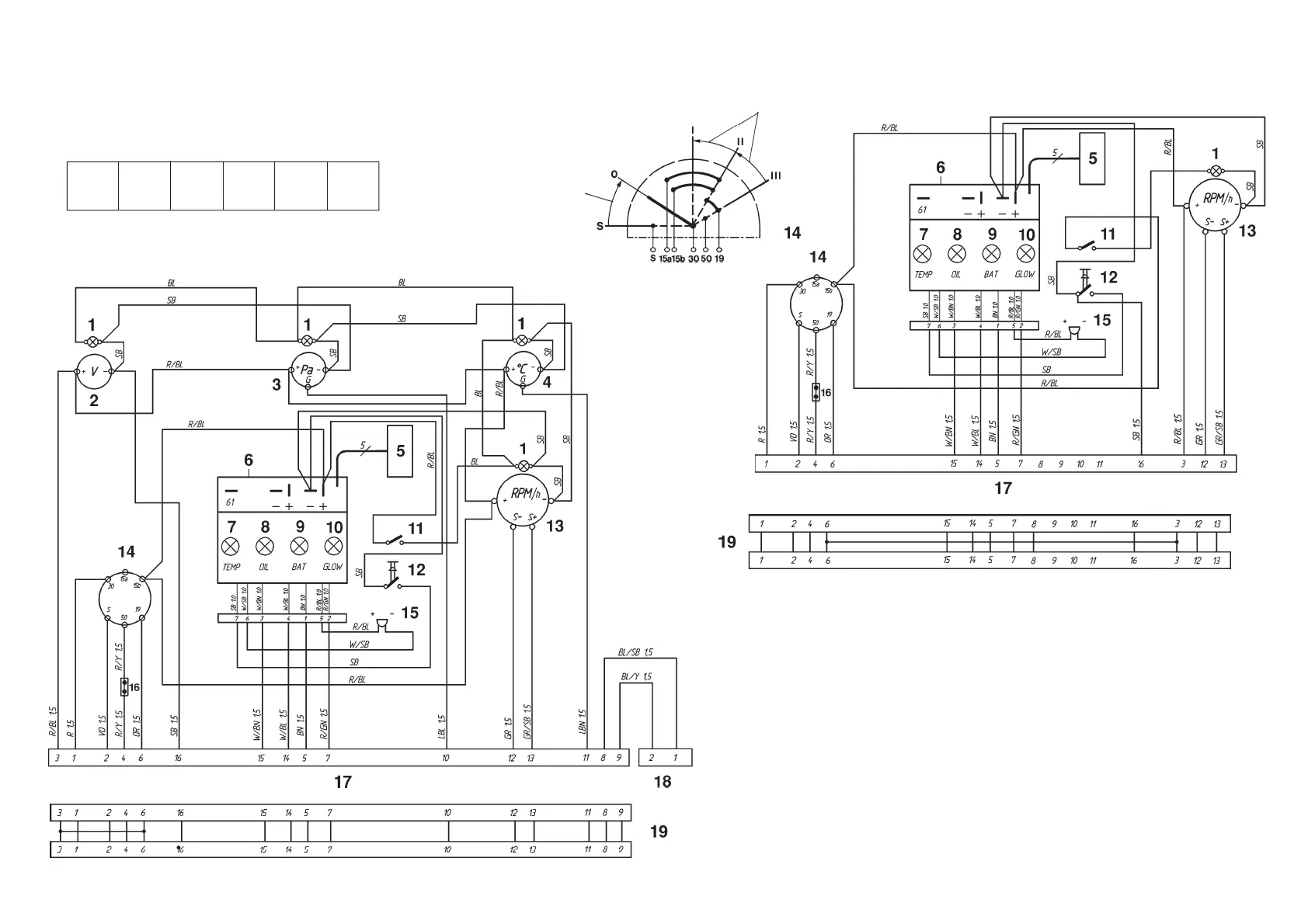
Instrument panel, (Main panel)
Spring loaded
Spring loaded
Control panel for auxiliary control position (Flying Bridge)
Instrument panels
1. Instrument lighting
2. Voltmeter
3. Oil pressure gauge
4. Engine coolant temperature (ECT)
gauge
5. Connector for connecting extra
warning display (accessory)
6. Control module (alarm)
7. Warning light, engine coolant tempera-
ture (ECT)
8. Warning light, oil pressure
9. Warning lamp, charging
10. Control lamp (not used)
11. Instrument lighting switch
12. Alarm test/acknowledgement switch
13. Tachometer with built-in hours run meter
14. Key switch
15. Alarm
16. Connector for connecting neutral position
switch
17. 16-pin connector
18. 2-pin connector (for supplementary panel)
19. Adapter