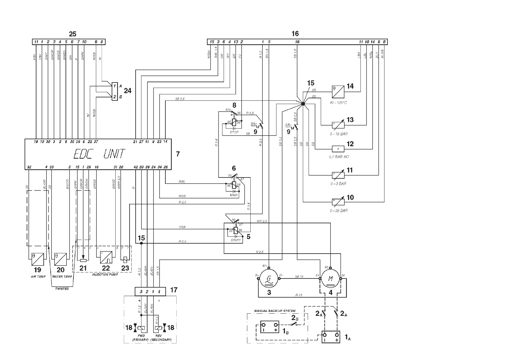
Engine (24V system voltage)
Note. The components in the wiring diagram
have the same numbers as shown in the key
diagrams on page 62.
1
A
. Starter battery
1
B
. Emergency-/auxiliary battery
2
A
. Main switch
2
B
. Main switch for back-up system
3 . Generator (GEN)
4 . Starter motor
5 . Starter relay
6 . Main relay*
7 . Electronic Diesel Control (EDC) control
module box
8 . Stop relay
9 . Semi-automatic fuses (8A)*
10. Oil pressure sender, reverse gear.
11. Pressure sender, turbo pressure
12. Oil pressure switch, engine
13. Oil pressure sender, engine
14. Engine coolant temperature (ECT) sender
15. Joint
16. 16-pin connector, (instrument cable har-
ness)
17. 4-pin connector, (reverse gear)
18. Solenoid (reverse gear with electronic
shifting)
19. Temperature sender, charge air
20. Engine coolant temperature (ECT) send-
er, EDC
21. Position sensor,** control rod
22. Engine speed (RPM) sender
23. Electro-magnetic actuator, EDC**
24. 2-pin connector, data link connector
(DLC)*
25. 16-pin connector, (control)
* Located in the junction box
** Located on the governor
NO = Normally open during operation
Cable color
BL = Blue P = Pink
LBL = Light blue R = Red
BN = Brown SB = Black
LBN = Light brown VO = Violet
GN = Green W = White
GR = Gray Y = Yellow
OR = Orange
Cable areas in mm
2
are noted
after the color codes in the
wiring diagram.
The cable area is 0.5 mm
2
unless
otherwise stated.
The cable run marked with a dashed
line is not supplied by Volvo Penta.