Group
28
Ignition
systems
Design
and
function - System
descriptions
EZ-116K
2 1 4
147
'22
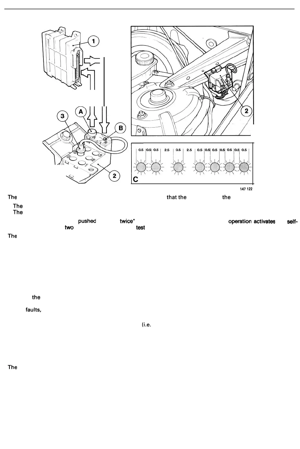
The
following
preliminary
steps
must
be carried
out
to
ensure
that
the
LED
displays
the
codes:
-
The
coding
cable
must
be
connected
to
socket
6.
- The
ignition
must
be
switched
on
without
starting
the engine (i.e. the key
must
be
turned
to
switch
position
II).
Pushbutton A must then
be pushed once
or
twice·
for not longer than 3 seconds. One operation activates the seIf-
diagnostic function and
t'NO
operations the functional test program.
The
following
fault
codes are
displayed
when
the
self-diagnostic
function
is selected:
1-1-1
No
faults.
1-4-2 Internal
control
unit
fault
;
engine
runs
with
timing
retarded to 'fail-safe' setting.
1-4-3 Faulty knock sensor;
engine
runs
with
timing
retarded
to
'fail-safe' setting.
1-4-4
No
load
signal
from
fuel system
control
unit.
2-1-4 Faulty
speed/position
pick-
up
signal.
2-2-4 Faulty
temperature
sensor
signal (engine runs
as
though
hotl.
2-3-4 Faulty
throttle
switch
signal;
engine
runs
with
timing
retarded to 'fail-safe' setting.
Once a fault code has been displayed, the
pushbutton
must
be operated again to
display
the
next
code. In
this
case, a
repeat
of
the
previous
code indicates
that
only
one
fault
is stored in the
memory.
The
memory
function
must
be
erased
when
any
faults present have been corrected. Since the
memory
accommodates
a
maximum
of
three
faults,
further
faults,
if
any,
cannot
be
displayed
until
the
first
three have been corrected and
the
memory
erased.
This
is car-
ried
out
as
follows:
-
Switch
on
the
ignition
without
starting
the
engine (i.e.
turn
key
to
position
II).
- Depress
pushbutton
A
for
at least 5 seconds.
- Wait
for
the
LED
to
light
(approx.
4-5
secondsl.
- Operate
pushbutton
A once
more
for
at least 5 seconds.
Start and run
the
engine
up
to
normal
working
temperature. Stop the engine,
switch
on
the
ignition
and
operate
pushbutton
A
to
check
that
no
further
faults are present
in
the
memory.
The LED
should
display
the
code
1-1-1.
The
functional
test
program
is selected
by
operating
pushbutton
A
twice
after the
preliminary
steps have been car-
ried out. The LED
will
flash
continuously
at
a frequency
of
approx. 6 flashes
per
second,
indicating
that
the
control
unit
is
in
the
functional
test
mode.
The
following
acknowledgement
codes
may
then
be
displayed
:
3-3-4
Throttle
switch
1-4-1 Speed/position pick-up
The
acknowledgement
code
indicating
that
the
throttle
switch
and
its
wiring/connections
are
intact
is
displayed
by
pressing
the
accelerator
to
the
floor. The speed/position pick-up
acknowledgement
code
is
then
displayed
by
releas-
ing
the accelerator and
starting
the engine.
65