Group
28
Ignition
systems
Des
ign
and
function
-
System
descriptions
"2'
1.rt!..1f
4
'"
•
R
~
Jr. A
A®
I~
1.rt!..1f
IJr. A
D
lU1ZJ
Diagnostic
unit
-
Construction
and
signals
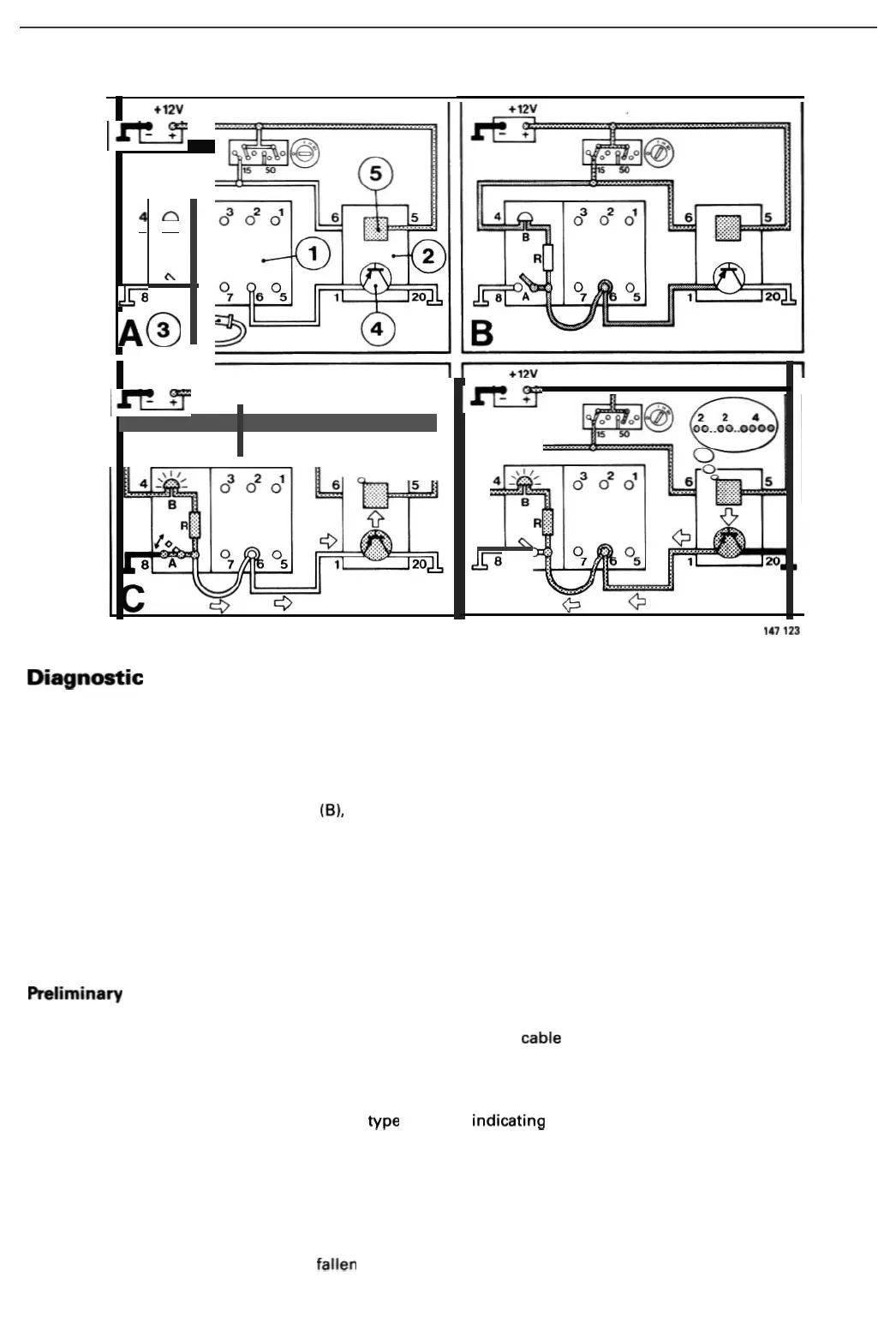
The above figures illustrate
the
construct
ion
of
the
diagnost
ic
un
it (1
),
its connections, and
the
sequence
of
events
which
occurs in
the
course of
commun
ication between
the
un
it and
the
igni
tion
system
contro
l
unit
(2)
during
fault
tracing.
Construction
and
connections
(Picture
AI
The
diagnostic
unit
consists of an LED (B), a resistor (R) and a normally-open switch (push
button
A)
.
Terminal
8 is
connected to
ground
when
the
switch
is
closed. A connec
tion
point
for
the
coding
cable (3) is
provided
between
the
resistor and switch. Socket
No.6
is connected
to
terminal
1 on the
ignition
system co
ntrol
unit
.
Grounding
of
terminal
1 is
monitored
by
a signal transistor (4) (actually a
transistor
network,
although
symbolized
by
a single
component
in the figures)
which
alternately opens and closes the
ground
connection across control
unit
ter·
mina!
20
. The signal
transistor
is
controlled
by the diagnostic
circuit
(5)
in
the control unit.
The battery supplies
power
to
control
unit
terminal 5 and to the
diagnostic
circuit
in the
control
unit
.
This
ensures
that the
memory
is
not
erased
when
the
ign
iti
on
is switched off.
Preliminary
steps
(
Picture
B)
Power
is
supplied
to
c
ontrol
unit
term
inal 6 across
ign
i
tion
sw
itch
term
inal
15
when
the
key is
turned
to
posit
i
on
II
.
Voltage is present at
termina
l 1 on
the
control
unit
when
the coding cable is inserted
in
socket
No
. 6
on
the
diagnostic
unit
.
Signal from diagnostic: unit
(Picture
Cl
The control
unit
must
be
supplied
with
some
type
of
signal indicating
which
of
the
test
functions
is
to
be activated.
This
information
is
supp
lied across the
normally-open
switch (pushbu
tton
A).
(The direction
of
the
arrows
in
this
picture
shows
that
the signal
flows
from
the
diagnostic
unit
to
the
cont
rol
unit
.)
The
switch
is
closed
by
depressing the
pushbutton
,
grounding
terminalS
on
the
diagnostic
unit
. Current
then
flows
from
the
battery
, across
ign
i
tion
switch
terminal
15
,
through
the
diagnostic
unit
and
finally
to
ground
across
terminal
8. This causes the LED
to
light
,
while
the
voltage
normally
present at control
unit
terminal
1 falls to 0 V. The control
unit
determines
whether
the self-diagnostic functi
on
or
functional test
program
has been selected
by
detecting
whether
the
vo
ltage at
term
inal 1 has fallen
to
zero once
or
twice
.
66