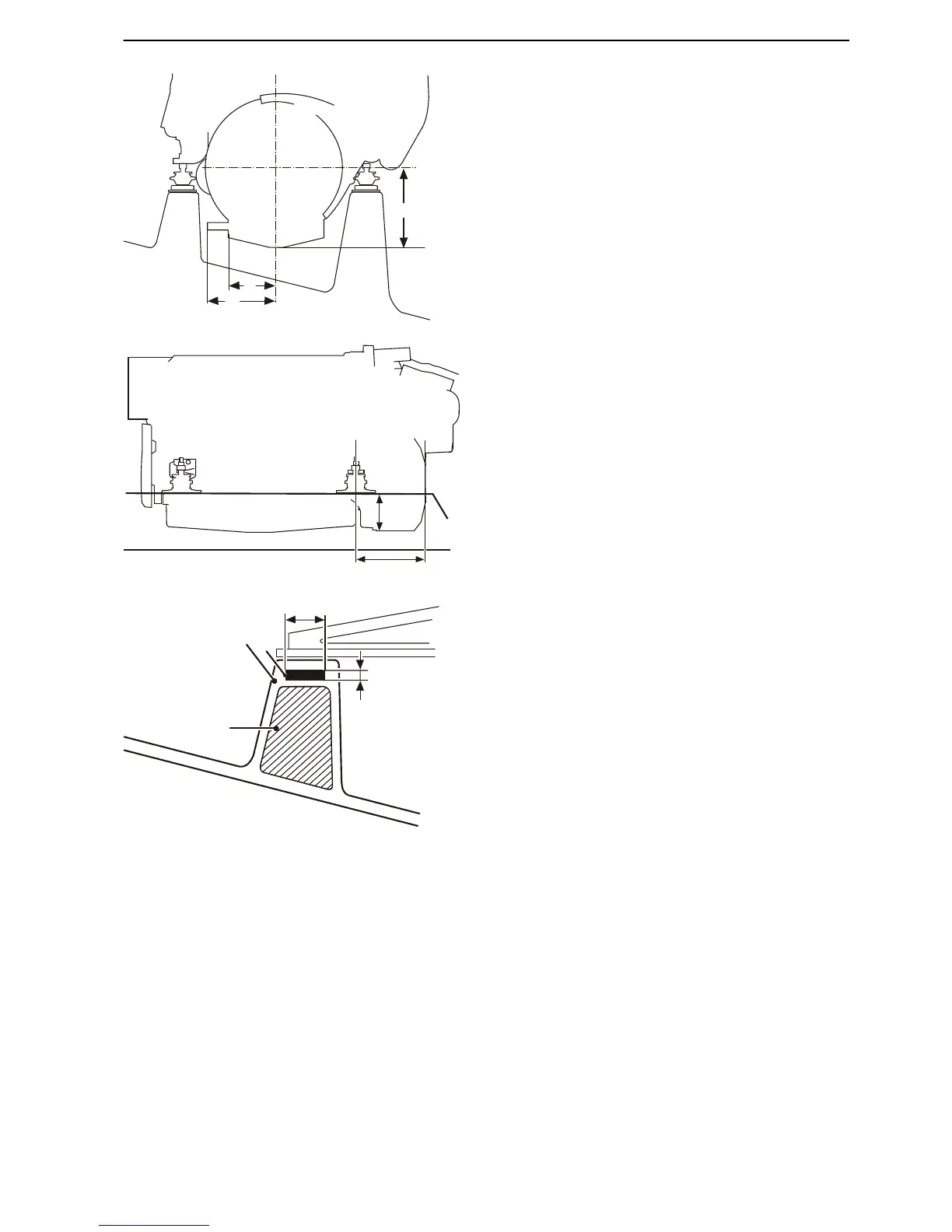
Engines should have a clearance of at least 20 mm
(3/4").
Make sure to leave space for protruding parts.
A 303 mm (11.92")
B 182 mm (7.16")
C Oil level sensor (option): 260 mm (10.24")
D 169 mm (6.65")
E Flywheel housing: 213 mm (8.39")
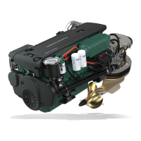
Construction
Build up the bed until it touches the drilling jig along the
entire length of the stay.
Use a suitable core material and laminate according to
current standards (e.g. ISO 12215). Build a galvanized
iron strip into the laminate for the engine mounts. Also
build in drainage channels so that bilge water is able
to run down to the bilge pump.
1 Core material
2 Fiber glass
3 Iron strip
A min 80 mm (3.1")
B 10 mm (0.4")
Holes for engine mounts
Fit the pins for the special tool in the forward and aft
engine mount holes for the engine model concerned.
Slide the drilling jig so that it contacts the pins. Drill 6
mm (1/4") pilot holes through the tool drill bushings into
the bed.
The outer holes are for D13 engines, the inner for D11
engines.
Installation, Volvo Penta IPS
47704162 10-2014 © AB VOLVO PENTA 85