IVTM
3
System Description
Wheel modules
Select wheel modules and counterweights according to their axle configuration.
The table contains components for three vehicle type examples. Further informa-
tion in chapter "Components", see chapter 4, page 16.
Order
Number
Component Comment 4x2 6x2 Articulated
bus 6x2
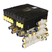
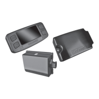
446 220 012 0 ECU Communication with trailer
ECU / warning lamps
1 1 1
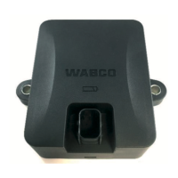
446 221 000 0 Display
1 1 1
894 607 390 0 Wiring harness Cable set, 7-pin
optional 894 607 295 0
(5-pin, no trailer-towing
operation)
1 1 1
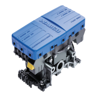
960 731 051 0 L shape wheel
module
for the front axle, rim 22.5",
10 holes
2 4 2
960 731 031 0 Wheel module for rear axle, rim 22.5", 10
holes
4 4 8
960 730 822 2 Counterweight Balance weight for front
axle wheel module
2 4 2
960 731 802 0 PA tube for front axle wheel module,
L-shape
2 4 2
960 731 822 2 PA tube for rear axle wheel module,
outside
2 2 4
960 731 804 0 PA tube for rear axle wheel module,
inside
2 2 4
960 731 801 0 PA tube Super Single 2 2 4
Table: 3-1: Components for bus / towing vehicle
Operation via CAN bus
Provided the trailer is equipped appropriately, data exchange can also be made via
CAN bus besides wireless connection between towing vehicle and trailer. Towing
vehicle ECU needs to be connected to vehicular CAN Bus for this purpose too.
Circuit diagrams
Detailed circuit diagrams are – as are the outline drawings of the components –
available on the Online Product Catalogue INFORM at http://www.wabco-auto.com
.
Enter wiring diagram product number for opening the file:
• 841 801 970 0: Solobus
• 841 801 971 0: Articulated bus
• 841 801 972 0: Articulated truck / truck
11