IVTM
6
Installation
35
Bus
The ECU plug must show up.
e roof frame in the cabin.
f the swivel joint.
rances
• in the roof lining
• with articulated buses, in the rear area of the front section (in the geometric
centre of all axles)
• with touring coaches, also in the ceiling of the luggage compartment
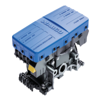
Mounting the ECU
– Read the chapter, see chapter 4.2 "Electronic Control Unit (ECU)", page 19.
– Mount ECU so that the distance to the wheel modu
les is as equal as can be.
Select distance to truck driver's cab such that length of ECU cable (8 m) is suffi-
cient to reach driver's cab.
us and t
-
ing good radio contact the ECU should not be shielded off by metal walls in its
direct vicinity, e.g. by a U-section.
tion through the integrated antenna you particularly
dinal floor.
– Use bracket 960 901 050 4 see figure 4-5 "Bracket 960 901 050 4", page 20 on
w the bracket to the vehicle.
6.3 Wiring in towing veh
Proceed as follows to install the wires of the IVTM into the bus or the towing vehi-
cle:
– Read the chapter, see chapter 4.4 "Connecting cable", page 21.
– Select the appropriate
circuit diagram according to the chapter, see chapter 3.3
"Configuration for bus and towing vehicle", page 10.
– Attach display to support
supplied at a suitable attachment location.
The display must not necessarily be located inside driver's direct field of vision.
– Fit the diagnostic socket to a suitable attachment location and label it with "Di-
agnostic IVTM".
Locations where diagnostic ports are already located would be specially suit-
able as the attachment location.
– Install cables according to the wiring diagram using cable ties in parallel with al-
ready existing wiring harnesses.
Form large loops from long lengths.
– Turn off the ignition.
– In the fuse box, search for appropriate fused circuits or connect 5 A fuses "on
the fly" to terminals 15 (ignition) and 30 (U Batt). Designate the flying fuses with
"IVTM".
– Connect the cable set with the fuses. Connect the ground line to the ground
tac
– Connect display and ECU.
–
Use threaded rods fo
r hanging assembly at th
– Position ECU in solo bus in the vehicle's centre, on articulated bus in driving di-
rection in front o
Further possible installation positions are:
• in the roof rounding opposite to the ent
–
Attach ECU to roof area of
b
ECU longitudinal axis must be in parallel
o bottom of frame on truck.
with longitudinal vehicle axis. Maintain
Ensuring optimal radio recep
need to leave out the longitu
towing vehicle. Scre
Welding coul
d impair the stability of the frame.
– Tighten ECU to bracket using torque of 15±1.5 Nm.
icle/bus
con t.