IVTM
5
Operation
25
5 Operation
In this chapter, the handling of the IVTM system is described by means of the
WABCO display.
Additionally installed warning lamp indicates the same warning like the display.
Please refer to manufacturer's operating instructions when operating by means of
an integrated display.
5.1 Warning signals
levels are indicated. The al lam and the type of
audio signal indicate the severity of the fault:
• A red warning lamp (STOP) and audio warnings at one minute intervals in
re fault and the vehicle m mediately (potential dan-
ns and vehicle).
• A yellow warning lamp (turtle) nd audio warning signals at 10 minute inter-
vals indicate a more minor fault; the vehicle speed should be reduced and the
e corrected at the first opp
The faults detected by IVTM are saved in the ECU for diagnostic purposes.
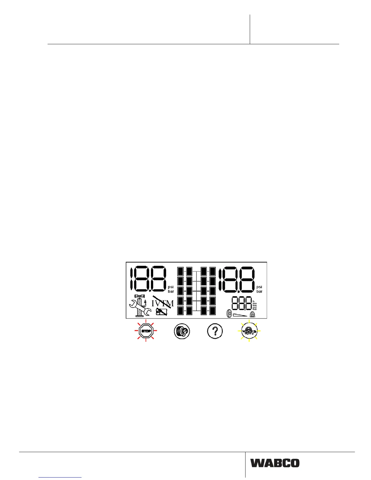
5.2 Switch on of ignit
After ignition is switched on, system performs an internal check procedure whe
all internal functions are tested. All symbols are displayed for one second, all pilot
lights and audio signals are enabled. This procedure is repeated twice.
Different alarm colou
r of the sign
di-
cate a seve
ger for perso
us
t be stopped im
a
tire pressur ortunity.
ion
re
fig. 5-1: Initialisation