5-24 BA ET18, 20, 24 en* 1.5 * et18_20_24b510.fm
5 Operation
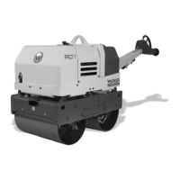
1. Raise the control lever base.
2. Make sure that the lever A is situated left under the driver`s seat in
position 1 .
3. Lower the control lever base.
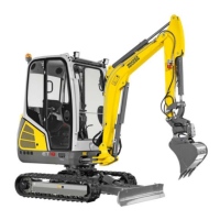
4. Raise the vehicle using the stabilizer blade and boom so far that no
contact with the earth exists and so that there are no foreign objects in
the travel gear during retraction or extension.
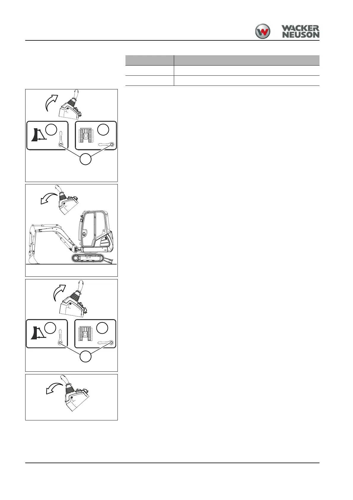
5. Raise the control lever base.
6. Bring lever A in position 2 .
7. Lower the control lever base.
Position Function
1 The stabilizer blade is actuated.
2 The telescopic travel gear is actuated.
Fig. 151Stabilizer blade/telescopic travel gear
A
1 2
Fig. 152Raising the machine
Fig. 153 Stabilizer blade/telescopic travel gear
1 2
A
Fig. 155Raising the machine
 Loading...