BA ET18, 20, 24 en* 1.5 * et18_20_24t900.fm 9-5
Technical data 9
9.8 Electrical system
Electrical components
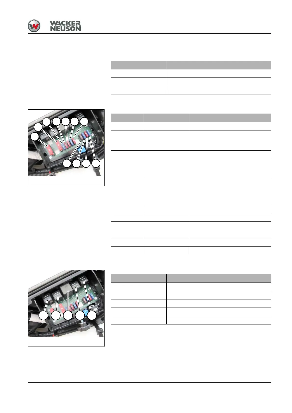
Fuses
The fuses are located behind the cover on the left.
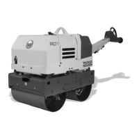
Relays
The relays are located behind the cover on the left.
ET 18/ET 20/ET 24
Alternator 12 V 55 A
Starter 12 V 1.1 kW (1.5 hp)
Battery 12 V 44 Ah
Fig. 283Fuses
F2
F1
F10
F11 F6 F9 F5
F3 F4 F7 F8
Fuses Rated current (A) ET 18/ET 20/ET 24
F1 50 A Starter, cutoff solenoid, socket
F2 50 A
Starter, air-pressure sensor/output
adaptation (Yanmar 3TNV80F-
SNNS1)
F3 7.5 A Display, cutoff solenoid
F4 15A
Valves, horn, high speed, hydraulic
quickhitch, upper carriage tilting,
automatic engine speed setting
F5 10A
Proportional auxiliary hydraulics
(AUX I)
Proportional 3rd control circuit (AUX
II)
F6 10A Heating, overload, driving signal
F7 10A Lights
F8 15A Lights
F9 15A Wiper, radio, interior light
F10 15A 12 V power outlet
F11 10A Rotating beacon, radio
K7 K9 K51 K58 K17
Fig. 284Relays
Relays ET 18/ET 20/ET 24
K7 Starting relay
K9 Cutoff solenoid
K51 Idling speed
K58 High speed (2nd travel speed)
K17 Hydraulic quickhitch