EasyManuals Logo

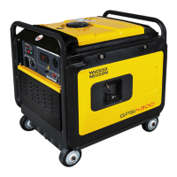
Wacker Neuson GPi 3200 User Manual

Wacker Neuson GPi 3200
76 pages
To Next Page IconTo Next Page
To Previous Page IconTo Previous Page
Page #71 background imageLoading...
Page #71 background image
GPi 3200
/4300
Schematics
9.4 Electrical Schematic Components-(CSA)
Ref.
A
B
c
D
E
F
G
H
J
K
L
M
N
0
Blk
Blk/W
Blu
LBiu
y
Pur
wc_tx001876gb.fm
Component
Ref.
Component
Engine
p
Engine switch
Generator
Q
AC
receptacle, 120V 20A
Control panel
R
Ground terminal
Diode rectifier
s stepping motor
DC Winding T Oil level sensor
Coil (1)
u Ignition coil
Coil
(2)
v starting motor
Main
coil w
Battery
DC circuit breaker
X
Fuse, 10A
DC
output terminal
y
Relay
Regulator
z
AC
receptacle, 120V 30A
Key switch
AA
Circuit breaker
Inverter and engine control unit
BB
Spark plug
Monitor control unit
-
-
Wire Colors
Black Brn
Brown
Black/White
Brn/W
Brown/White
Blue
Grn Green
Pink
Grn/W
Green/White
Yellow
W/Bik
White/Black
Purple
-
-
69
Org
Gry
R
w
Grn/Y
-
Orange
Gray
Red
White
Green/Yellow
-
W"CKEit
NEUSON

Table of Contents

Questions and Answers:

Question and Answer IconNeed help?

Do you have a question about the Wacker Neuson GPi 3200 and is the answer not in the manual?

Wacker Neuson GPi 3200 Specifications

General IconGeneral
BrandWacker Neuson
ModelGPi 3200
CategoryPortable Generator
LanguageEnglish

Related product manuals