Section 2
Auto-Zone CV & CV-EX
2-20 Installation and Wiring
MiniLink Interface
The MiniLink Interface is only required and used with the CV-EX system. It is not
required for the CV system. It functions as the loop master for each CV-EX system local
loop. With the CV-EX system, each local loop of CV controllers (maximum of 30) is
connected to a MiniLink. Two MiniLinks are supplied with the standard CV-EX system.
This allows up to 60 CV controllers (30 maximum per local loop) to be tied together to
form an integrated system. A CV-EX expansion kit is available which provides another
MiniLink to allow an additional 30 CV controllers to be connected to the system. A
maximum of two expansion kits can be used on the CV-EX system to provide integration
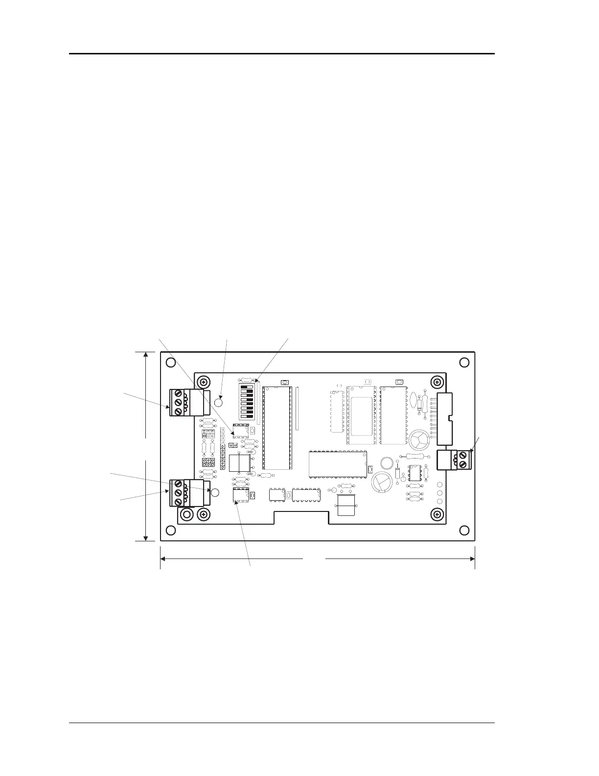
of up to 120 CV controllers. See Figure 2-15 for an overview of the MiniLink.
Figure 2-15: MiniLink Interface Overview
RN2
HIGH SPEED LOOP
R
INTERFACE
YS101697
T
U10
CX4
U4
RAM
CX3
U2
CX2
U3
EPROM
R6
R5
WDOG
U9
U8
R14
R15
R13
R12
TB1
R
R10
LOOP
R11
T
JO2
32
JP1
U5
2
16
8
4
U1
CX1
1
R1
ADDR
JO1
J1
R3
R2
NETWORK
TB2
R
T
24 VAC
Power
Network Loop
Communications
Driver Chip
Network Loop
Communications
LED
Local Loop
Communications
LED
Local Loop
Communications
Driver Chip
Address Switch
( Each Board Must Be Addressed Uniquely )
( 1,2,3,4)
Switch Shown Set For Address 1
Local Loop
Connector
Network Loop
Connector
7.50”
4.50"