Auto-Zone CV & CV-EX
Section 4
Start-Up and Troubleshooting 4-5
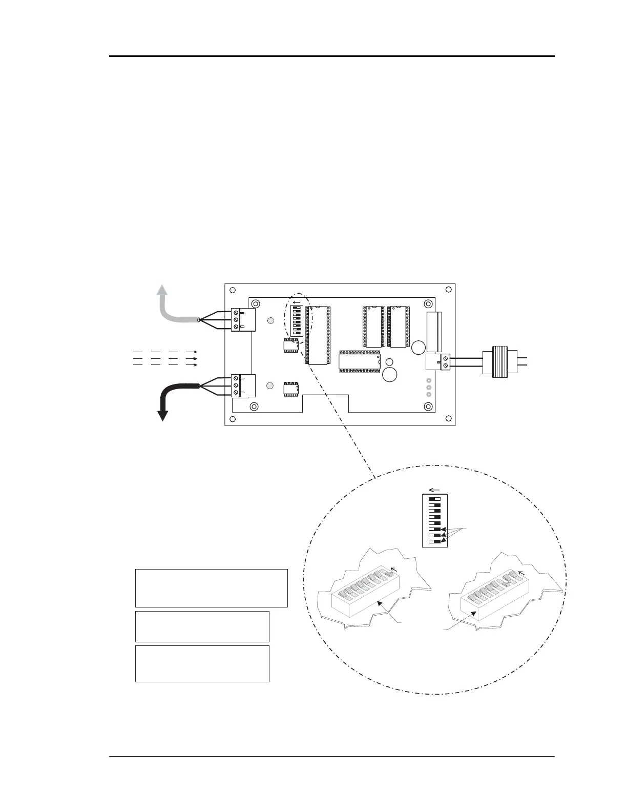
MiniLink
The MiniLink communications interface is only required when you are installing a CV-
EX system. It is not required for the CV system. It’s address switch must be set cor-
rectly, it must be correctly wired into the system and powered up in order for the CV-EX
system to operate correctly. The address switches must be set and the power cycled in
order for the address to be recognized by the system. See Figure 4-4 for MiniLink wiring
and addressing.
Figure 4-4: Communications Loop Wiring
Notes:
16
32
8
4
2
1
Caution!
The MiniLinks Must Have Address Switches Set Between 1
And 4 (Up To 4 MiniLinks Are Allowed Per CV-EX System).
The MiniLinks Should Be Addressed In Consecutive Order
Starting With Address #1. Address #1 Must Be Present On
The Loop For The System To Function.
Address Switch Shown Is
Set For Address 1
Address Switch Shown Is
Set For Address 4
MiniLink
Address Switch
These Switches Must Be
In The OFF Position
As Shown
Note:
The Power To The MiniLink Must Be Removed And
Reconnected After Changing The Address Switch
Caution:
Disconnect All Communication Loop Wiring
From The MiniLink Before Removing Power
From The MiniLink. Reconnect Power And Then
Reconnect Communication Loop Wiring.
ADD
ADD
ADD
The Address For Each MiniLink
Must Be Unique To The Other MiniLinks
On The Network Loop. Loop #1 MiniLink
Should Be Addressed As #1
Loop #2 MiniLink Should Be Addressed
As #2 Etc..
1.)24 VAC Must Be Connected So
That All Ground Wires Remain
Common.
2.)All Wiring To Be In Accordance
With Local And National Electrical
Codes And Specifications.
3.) All Communication Wiring To Be
2 Conductor Twisted Pair With
Shield. Use Belden #82760 Or
Equivalent.
R
SH
T
R
SH
T
R
SH
T
R
SH
T
All Communication Loop
Wiring Is Straight Through
Required VA For Transformer
MiniLink = 10VA Max.
See Note 1.
LOOP
MINILINK
24VAC
GND
T
SH
R
32
16
8
4
1
2
OFF >
Rocker Down
Local Loop
RS-485
9600 Baud
(See Note 3).
Connect To CV
Controller or
System Manager
On Local Loop
Connect To Next
MiniLink And/Or
CommLink On
Network Loop
Network Loop
RS-485
19200 Baud
(See Note 3).
Line Voltage
24VAC
GND
Minilink Communications Interface
ADD
NETWORK
SH
T
R