Section 4
Auto-Zone CV & CV-EX
4-4 Start-Up and Troubleshooting
CommLink
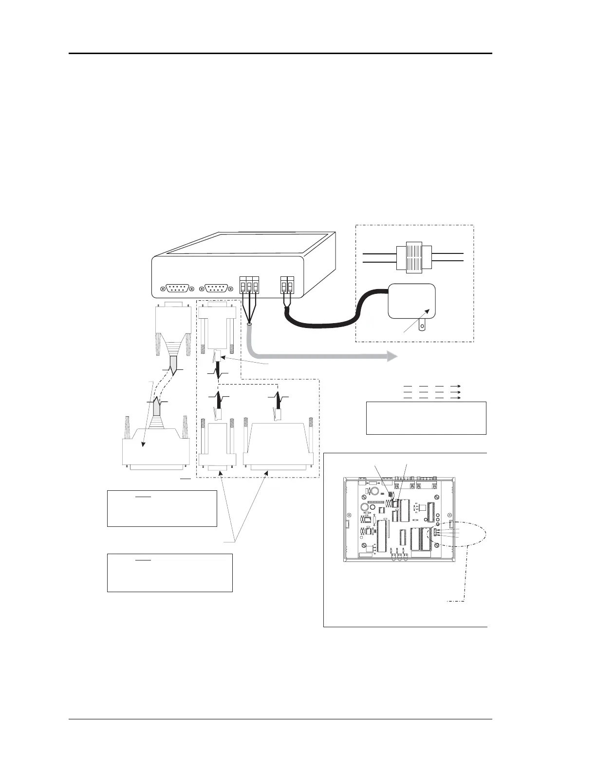
As previously described, the CommLink is the local loop master for the CV system and
the network loop master for the CV-EX system. For both systems to function the
CommLink must be set to the correct operation mode by setting the correct jumper
position on the CommLink board. Also the CommLink communications must be wired
correctly to the system and connected correctly to the computer (if used) and Remote
Link. It must also be powered up in order for either system to communicate. See Figure
4-3 for information.
Figure 4-3: CommLink Wiring & Jumper Settings
Notes:
R
SH
T
R
SH
T
R
SH
T
R
SH
T
All Communication Loop
Wiring Is Straight Through
Caution:
Disconnect All Communication Loop Wiring
From The CommLink Before Removing Power
From The CommLink. Reconnect Power And Then
Reconnect Communication Loop Wiring.
For CV-EX Systems Connect To First
MiniLink On Network Loop. On CV
Systems Connect to the First CV
Controller on Local Loop
Network Loop
RS-485
19200 Baud
Local Loop
RS-485
9600 Baud
Line Voltage
See Note 1
24VAC
Required VA For Transformer
CommLink = 14VA Max.
CommLink Is Supplied With 110/24VAC Power Supply.
If Desired A Transformer (By Others)
May Be Wired To The CommLink Instead. See Note 1.
COMMLINK II COMMUNICATIONS INTERFACE
(Multiple Loop or Single Loop)
Molded Modem Cable.
Supplied With CommLink
(DTE)
REMOTE LINKREMOTE
LINK
485 LOOP485
LOOP
COMPUTER
(DCE)
GT
R
G
2
V
4
D
N
POWER
4 Piece Computer
Cable Kit. Supplied
With CommLink
Use 25 Pin Or 9 Pin Connector As Required By
Available Serial (COM) Port On Computer.
Connect To Remote Link .Only
9Pin
Female
9 Pin
Female
25 Pin
Female
9Pin
Female
120/24 Vac
Transformer
25 Pin
Male
Warning: Use The “Molded Cable” To
Connect To The Computer (DCE) Connector
Or Serious Damage To The CommLink Could
Result. This Cable Is Only To Be Used To
Connect From The CommLink (DTE)
Connection To The Remote Link (When Used).
Do Not
Warning: Use The “25 Pin Or 9 Pin Cable”
To Connect To The Remote Link (DTE) Connector Or
Serious Damage ToThe CommLink Could Result.
This Cable Is Only To Be Used To Connect From The
CommLink (DCE) Connection To The Computer
Do Not
Connect Supplied RJ12 Modular Phone Cable
To Supplied 9 Pin Or 25 Pin Connector As Reqd
By Your Computer Com Port Connection
1.)24 VAC Must Be Connected So
That All Ground Wires Remain
Common.
2.)All Wiring To Be In Accordance
With Local And National Electrical
Codes And Specifications.
Note:
Place Jumper Between Between
Pins 2 & 3 For The CV (Single
Loop) System. Place Jumper
Between Pins1&2ForTheCV-
EX (Multiple Loop) System.
3.)Network and/or Local Loop
Communication Wiring To Be 2
Conductor Twisted Pair With
Shield. Use Belden #82760 Or
Equivalent.
COMM DRIVER CHIP
(U1)
PIN 1
MULTI
SINGLE
1
2
3
CommLink Jumper Switch Settings