Auto-Zone CV & CV-EX
Section 4
Start-Up and Troubleshooting 4-7
CV Controller Communications
One CV controller is required for each Constant Volume AHU unit to be connected to the
system. As with the communications devices on the system described previously, it must
be wired correctly and it must be connected to 24 VAC power for the system to function.
Each controller must also be addressed correctly. Improper addressing is one of the most
common mistakes made when installing a CV or CV-EX system. If duplicate addresses
are assigned on the same loop, fluctuating readings will occur. Fisrst one controllers
setpoints and status will be passed and then the other. This can be a very frustrating error
to find. Another common mistake is flipping (reversing) of the T and R wires on the
communication loop between controllers or other communications devices. Always be
sure to double check all communication wiring and addressing before initial
commissioning of the system. It is musch easier to set the address switch on a controller
prior to installation rather than after it is installed in a ceiling or rooftop unit control
panel. The address switches must be set and the power cycled in order for the address to
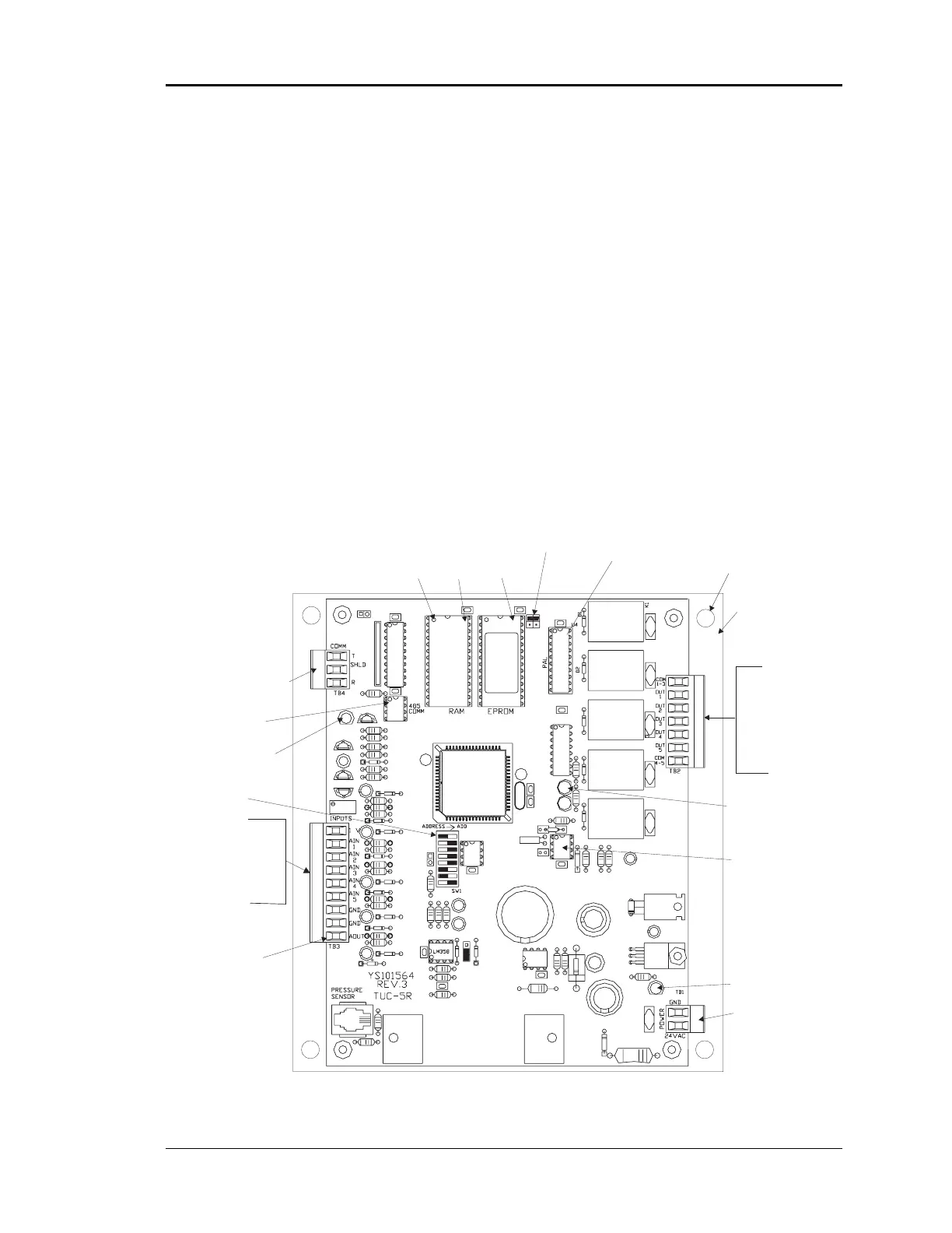
be recognized by the system. Please see Figure 4-6 and Figure 4-7 for CV controller
component location and addressing information.
Figure 4-6: CV Controller Component Locations
HVAC Unit
Connections
Fan
Heat/Cool 1
Heat/Cool 2
Heat/Cool 3
Heat/Cool 4
Diagnostic Blink
Code LED
RS-485
Communications
Loop Connection
Typical
Pin 1
Indicator
RAM
Chip
EPROM
Chip
PAL
Chip
RAM Size
Select
Jumper
RS-485
Communications
Driver Chip
Real Time
Clock Chip
Mounting
Backplate
Mounting Hole
Typof4
Comm
LED
Address Switch
(Set Between
1 & 30)
Analog Inputs
Space Sensor
Slide Adjust
Supply Air Temp
Outdoor Air Temp
Auxiliary Alarm
Analog Output
0-10 VDC
Economizer
Power LED
24 VAC
Power Input