Auto-Zone CV & CV-EX
Section 4
Start-Up and Troubleshooting 4-23
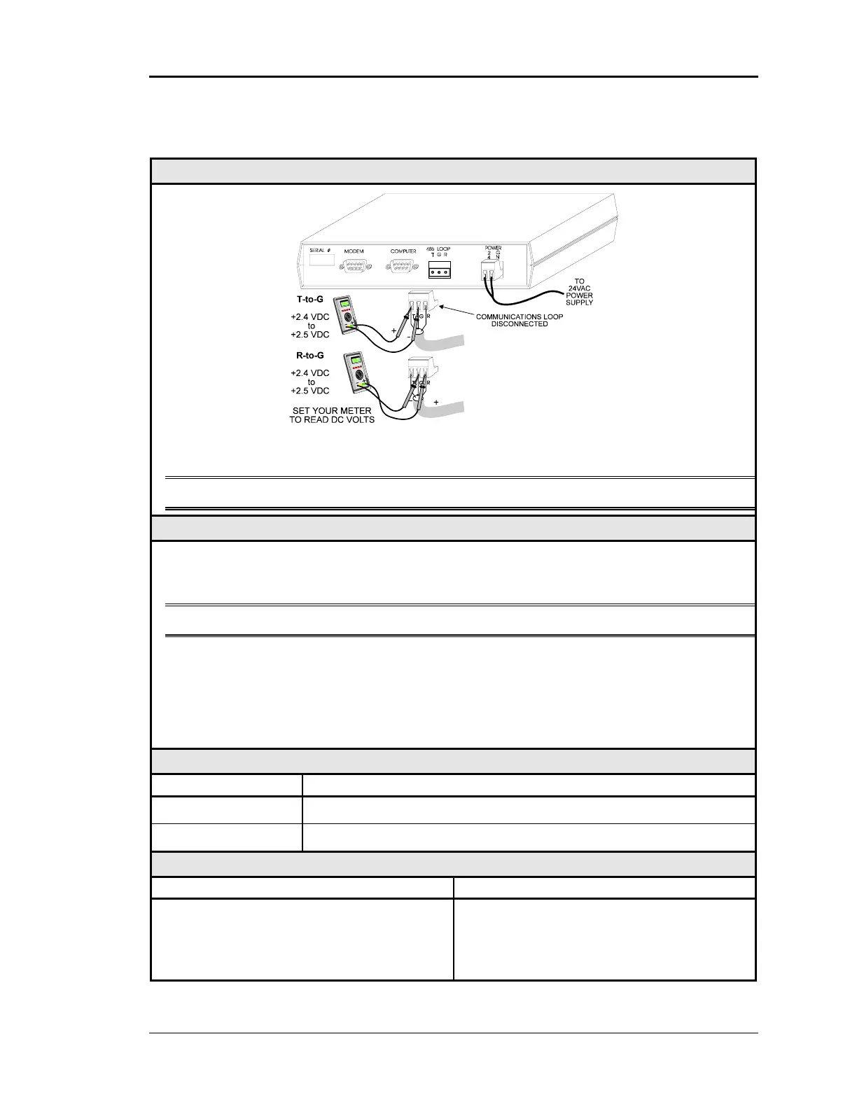
Checking CommLink Network Loop – CV-EX
Diagram
The indicated values are typical of a normal system, actual readings may deviate slightly
due to the number of units connected and other system specific factors.
Note: All of the connected CV controllers should be powered up for this test.
Overvie
This is a “quick check” to determine if any of the driver chips on the Network loop are dam-
aged. Since all units will “float” both of their communications connections at about 2.45
Volts, you can quickly check the entire Network loop by unplugging it at the CommLink II.
Note: Be sure that the loop you are testing does not have a short circuit from T to R.
Tip The Loop LED (located on the front panel) should “flicker” when the CommLink is
attempting to communicate with the MiniLinks. There is a noticeable change in the
flicker when the loop is disconnected, if you observe a normal functioning unit. When
the loop is reconnected it may take up to 60 seconds before the CommLink re-
establishes communications with the MiniLinks.
Measurements
Network Loop Acceptable Range
T - G (SHLD) 2.4-to-2.5 Volts DC
R - G (SHLD) 2.4-to-2.5 Volts DC
Action
Condition Action
If voltages are too high or too low on either
side
1. One or more of the MiniLinks has a
damaged Network driver chip. Disconnect
Zone Managers one at a time to isolate the
problem. See Figure 4-9.