Section 4
Auto-Zone CV & CV-EX
4-28 Start-Up and Troubleshooting
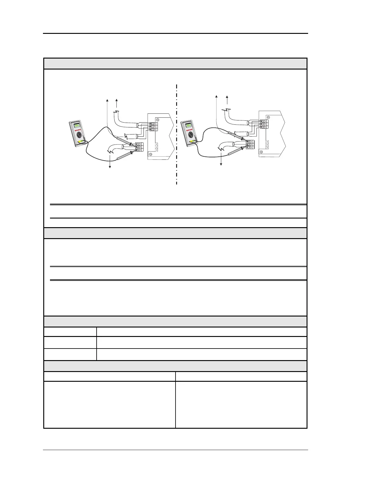
Checking the Local Loop at the MiniLink – CV-EX
Diagram
Meter Set To Read DC Volts
NETWORK
LOOP
G
T
R
G
G
G
T
T
T
R
R
R
+
-
+
-
+2.4 VDC
to
+2.5 VDC
R-to-G
T-to- G
NETWORK
LOOP
G
T
R
GT
R
+
-
+
-
+2.4 VDC
to
+2.5 VDC
To Other MiniLinks
Or CommLink
On The Network Loop
To Other MiniLinks
Or CommLink
On The Network Loop
MiniLink
MiniLink
To CV Controllers
And System Manager
On Local Loop
To CV Controllers
And System Manager
On Local Loop
The indicated values are typical of a normal system. Actual readings may deviate slightly
due to the number of units connected and other system specific factors
Note: These tests assume that the MiniLink being checked are powered up.
Overvie
This is a “quick check” to determine if any of the CV Units on a Local Communications
Loop are damaged. Since all CV Units will “float” their communications connections at
about 2.45 Volts, you can quickly check an entire loop by unplugging it at the MiniLink.
Note Be sure that the loop you are testing does not have a short circuit from T - R.
Damage typically occurs when the communications loop is exposed to excessive voltage, as
may occur during installation, due to wiring errors. The driver chips are socketed on all
boards to facilitate servicing. It is unusual for driver chips to fail during normal operation.
Almost all failures occur due to wiring related problems.
Measurements
Local Loop Acceptable Range
T - SHLD 2.4 - 2.5 Volts DC
R - SHLD 2.4 - 2.5 Volts DC
Action
Condition Action
If voltages are too high or to low on either
side
1. One or more of the attached controllers
has a damaged Comm Driver chip. See
Figure 4-9.
2. Wiring errors such as "crossed connec-
tions", short circuits, etc.