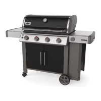
WWW.WEBER.COM
27
MAINTENANCE
330
21
12
11
9
18
19
17
20
13
14
15
16
23
22
10
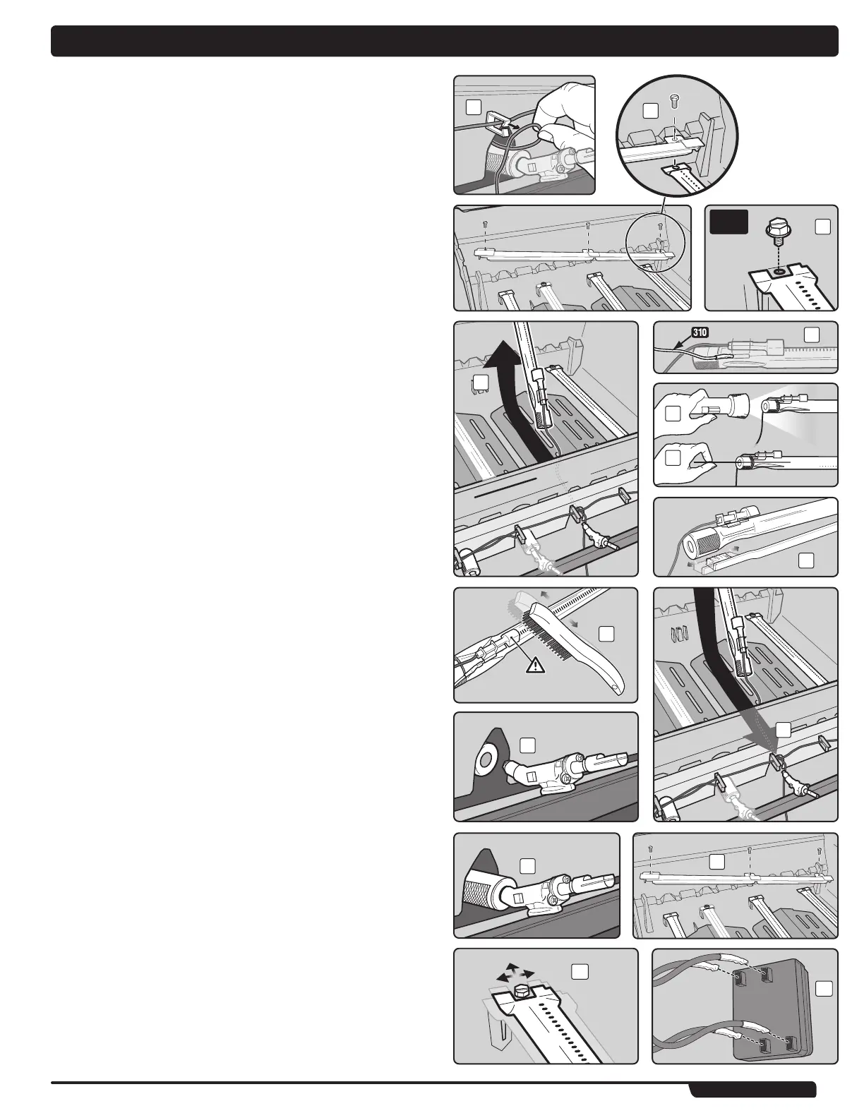
BURNER TUBE CLEANING OR REPLACEMENT (continued)
Remove Burner Tubes
You will need: A 5/16" spanner.
A) Remove igniter wire(s) from igniter clip(s) (9).
B) Using a 5/16" spanner, remove screws that secure Crossover
®
channel to inside
rear of cookbox (10).
C) Remove screw that holds burner tube to the cookbox using a 5/16" spanner (11).
D) Pull burner tube assembly (this includes igniter) up and out of cookbox (12).
Note: 310 units will have an additional earthing wire attached to the centre burner tube
(13).
Clean Burner Tubes
You will need: A torch, a wire (a straightened-out coat hanger), a suitable stainless steel
bristle brush, and a soft bristle brush (toothbrush).
A) Look inside each burner tube and Crossover
®
channel with a torch (14).
B) Clean any debris or blockage from the inside of the burner tubes and Crossover
®
channel with the wire(15).
C) Check spider/insect screens at the ends of the burner tubes and clean them using
the soft bristle brush (16).
m CAUTION: Do not clean the spider/insect screens with hard
or sharp tools. Do not dislodge the spider/insect screens or
enlarge the screen openings.
D) Use the stainless steel bristle brush to clean the outside of the burner tubes and
the Crossover
®
channel (17). This is done to make sure all burner tube ports
(openings) running along the length of the burner tubes are fully open. When
cleaning burner tubes, avoid damaging the igniter electrode by carefully brushing
around it.
Reinstall Burner Tubes
You will need: A 5/16" spanner.
A) Slide each burner tube and igniter wire through hole in cookbox (18). Refer to
“ELECTRONIC IGNITION SYSTEM OPERATIONS” for proper burner tube position.
B) Align burner tube with valve.
m CAUTION: The burner tube openings (19) must be positioned
properly over the valve orifices (20).
C) Re-install screws that hold the Crossover
®
channel to the cookbox using a 5/16"
spanner (21).
D) Re-install screw that holds the burner tube to the cookbox using a 5/16" spanner.
Burner tube may seem loose (22), when screw is snug. This is normal.
E) Route wires back through igniter clips. Refer back to figure (9).
m CAUTION: All wires must be properly routed through wire clips.
F) Attach wires to igniter module, following the numerical/colour coding (23). Refer to
“ELECTRONIC IGNITION SYSTEM OPERATIONS” for proper attachment of wires.
m WARNING: Make sure that all parts are assembled and
hardware is fully tightened before operating the grill. Your
actions, if you fail to follow this Product Warning, may cause
a fire, an explosion, or structural failure resulting in serious
personal injury or death as well as damage to property. ◆