Installation and Connection
English
For the correct connection of the control, use:
1. Gauge of the cables: 0.5 mm² (20 AWG) to 1.5 mm² (14 AWG).
2. Maximum torque: 0.5 N.m (4.50 lbf.in).
3. Wiring of the connector of the control board with shielded cable and separated from the
other wiring (power, command in 110 V / 220 Vac, etc.), according to item 3.2.6 Cable
Separation Distance on page 24. If those cables must cross other cables, it must be done
in perpendicularly among them, keeping the minimum separation distance of 5 cm at the
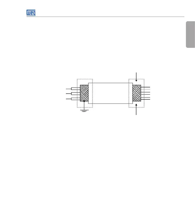
crossing point. Connect the shield according to the figure below:
Do not ground
Insulate with tape
Inverter
side
Figure 3.3: Shield connection
4. Relays, contactors, solenoids or coils of electromechanical brake installed close to the inverters
may occasionally generate interference in the control circuitry. To eliminate this effect, RC
suppressors (with AC power supply) or freewheel diodes (with DC power supply) must be
connected in parallel to the coils of these devices.
5. When using the external HMI (refer to chapter 7 ACCESSORIES on page 39), the cable that
connects to the inverter must be separated from the other cables in the installation, keeping
a minimum distance of 10 cm (3.95 in).
Buy: www.ValinOnline.com | Phone 844-385-3099 | Email: CustomerService@valin.com