E-36 | WG20 Geared Motors
18.6.1.Manual brake release
18.6.2.Locking device for the manual release lever
18.6.3.Rectier
1
2
3
4
5
6
7
8
9
10
11
12
13
14
15
16
17
18
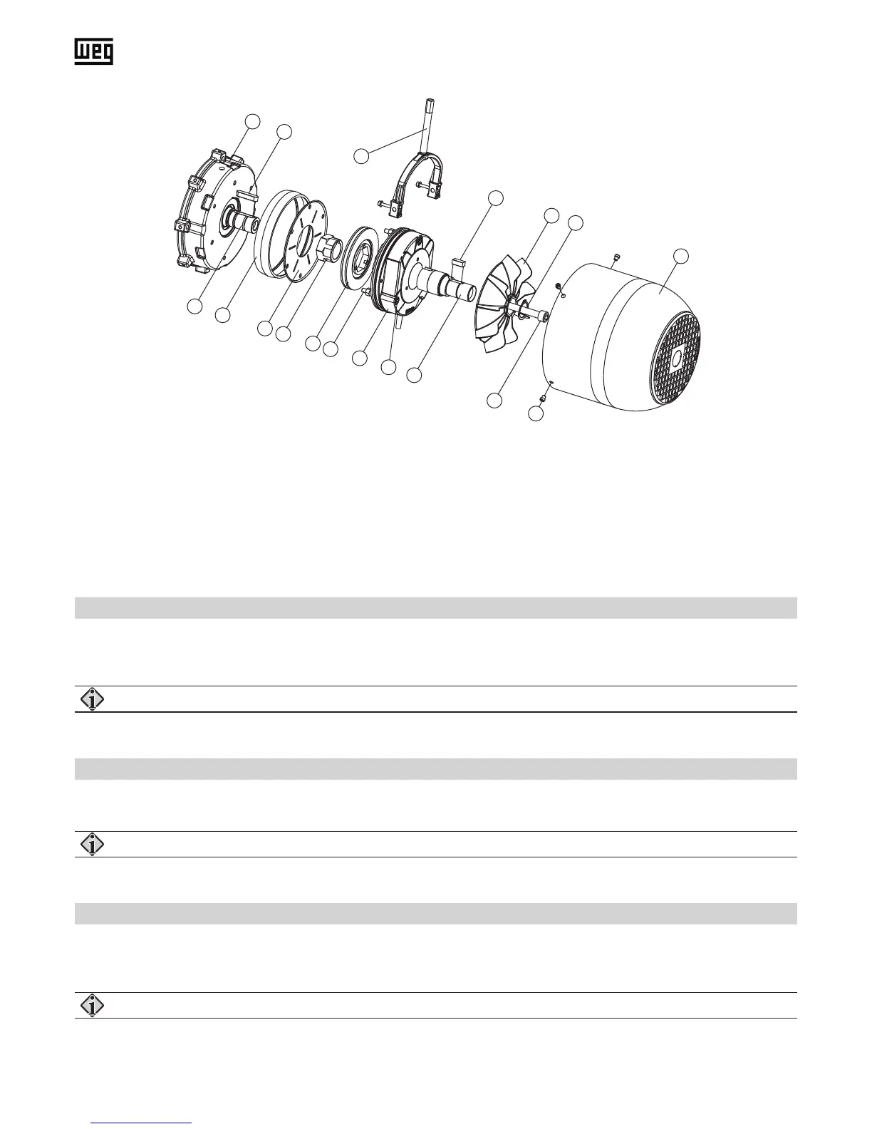
(1) Brake endshield
(2) Key
(3) Motor shaft
(4) Dust protection ring
(5) Friction plate
(6) Gear hub
(7) Manual release lever (optional)
(8) Brake disc with friction linings
(9) Sleeve screws
(10) Magnetic case
(11) Socket cap screws
(12) Key
(13) Brake shaft extension
(14) Fan
(15) Retaining ring
(16) Socket cap screw
(17) Fan cover screws
(18) Fan cover (brake execution)
It is used to lift the brake in case of a loss of power supply. By pressing the lever, the anchor plate is pulled to the magnet
and the brake is lifted.
For safety reasons the adjustment of the manual release must not be changed.
In case of service, the manual brake release can be xed with a locking device.
The motor may only be taken into operation after having deactivated the locking device.
Brake motors will be delivered as standard with connected rectier for AC-side switching. For DC-side switching the bridge
between terminals 5 and 6 must be removed and a switching contact must be connected.
Start-up of motor only with connected brake. (Check!)