E-18 | WG20 Geared Motors
7.3. Setting up the gear unit / geared motor
7.3.1.Gear unit ventilation
Minimum surface area „S“
of phase conductor (L1, L2, L3)
Minimum surface area
of corresponding ground connection
mm² mm²
S ≤ 16 S
16 < S ≤ 35 16
S > 35 0.5 x S
■ When installing please ensure that the unit is not exposed to any shocks or vibrations in order to avoid noise during
operation.
■ The mounting surface should be even and torsionally rigid.
■ Distortion of the gear case should also be avoided.
■ Reduce reaction torque with a torque arm or a rubber buffer kit (no rigid joints).
■ Input and output elements have to be equipped with a contact protection.
■ When installing the motor, ensure that the intake is not obstructed and air can circulate freely. Do not remove the fan
blade or cowl, or enclose the motor with a casing because in both cases, there would not be enough air for cooling and
the motor could overheat.
Gear unit with vent plug:
Oil drain plugs and vent plugs must be fully accessible!
The vent plug with transport locking device is installed at the proper position for the mounting position.
Following gear unit sizes are equipped with a vent plug:
■ C07, C08
■ F06, F07
■ K06, K07
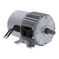
Activating the vent valve:
The vent valve is to be activated before the unit is put into operation by completely demounting the transport
protection (rubber clip) as described below.
Remove the rubber clip completely before start-up!
Figure 1: Information label (red) on the gear unit
Table 2: Minimum surface area
Please note the following when connecting-up:
■ The contact surface must be clean and bright, and protected with a suitable anti-corrosion agent, e. g. acid-free Vaseline.