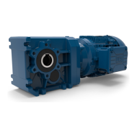
WG20 Geared Motors | E-19
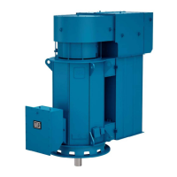
7.3.2.Geared motor with backstop
7.3.3.Gear unit with solid shaft
7.3.4.Installation and demounting of hollow-shaft gear units
The backstop allows the operating in only one rotating direction. The free rotating direction is marked with a rotating direc-
tion arrow at the output of the gear or on the ventilation cover of the motor.
A start-up of the motor with full power consumption against the locking direction of the gear will lead to destruction
or damage of the backstop.
The free rotating direction has to be checked before the start-up.
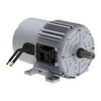
Geared motor with a backstop at the motor:
Using gears with backstop, the rotating direction of the e-motor and the mains are to be detected with a meter. Mind the
rotating direction arrow on the housing! On motors, which are winded 400/690 Volt, the rotating direction can be detected
through a short-time start-up in star connection.
The output shafts are manufactured with a diameter of 50 mm in ISO k6 tolerance class and beginning at a diameter 55
mm in ISO m6 tolerance class.
All output shafts are equipped with DIN 332 tapped centre holes that are used to tighten the transfer elements.
All output shafts are provided with a corrosion protection product upon delivery. This product must be removed with a
conventional solvent.
■ The solvent must not be allowed to come into contact with the shaft seals!
■ Make certain to prevent all impacts and mechanical shocks on the end of the shaft since the output bearing
system can be damaged.
■ Mechanical drive elements that apply radial forces to the output shaft must be installed as close as possible to the
output shaft bearings!
■ Add-on power transfer elements should balance and must not cause any unacceptable radial or axial forces
(see Catalogue for acceptable values).
Concerning the design of the customer’s shaft please mind the construction references in the latest geared motor
catalogue.
Assembling: (see Figure 2 and Figure 3)
The hollow-shaft gear units must always be installed in such a way that no axial forces are applied to the output shaft
bearing system.
1. Check the machine shaft (3) on possible damages like e.g. notches or upsettings.
2. Clean the customer’s machine shaft (3) thoroughly before the mounting.
Gear drives lacking a vent plug:
Sealed-design gear drives are supplied without a vent plug.
This applies to the following gear unit types:
■ C00, C01, C03, C05, C06
■ F02, F03, F04, F05
■ K02, K03, K04, K05