WG20 Geared Motors | E-35
18.4. Temperature controller Bimetal switch „NC contact“ (TH)
18.5. PTC Thermistor protection (TF)
18.6. Brake
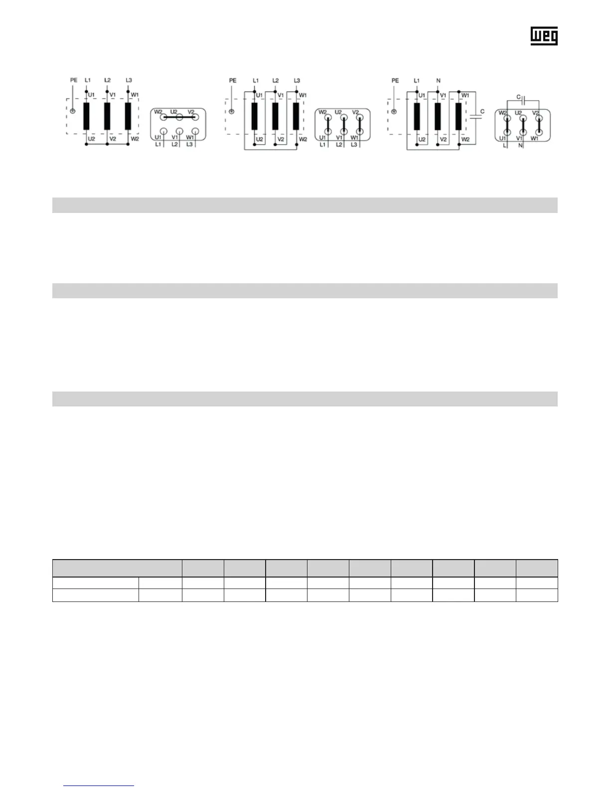
U1 = black V1 = light blue W1 = brown
U2 = green V2 = white W2 = yellow
Thermostats have small bimetallic strips that make or break a contact when the critical temperature is reached. The break
contact opens the eld circuit and disconnects the power supply to the motor. Thermostats are only available for motor
series 11 (frame sizes 63 to 132).
Block terminal designation in the terminal box: 2TB1 / 2TB2 (see page E-33)
PTC thermistors are semi-conductors whose electrical resistance increases dramatically when the critical temperature is
reached.
In addition to the PTC thermistor, a control unit is also required. The relay in the tripping unit has a changeover contact,
which can either be used to open the excitation circuit in the motor contactor or trigger a warning signal.
Block terminal designation in the terminal box: 2TP1 / 2TP2 (see page E-33)
The single-disc brake is released electrically. The brake is applied mechanically when the voltage is switched off.
At delivery the brakes are adjusted to the brake torque.
Connecting the brake:
Connect the brake control system according to the circuit diagram supplied with the brake.
Maintenance:
DThe spring-loaded brakes hardly need any maintenance. The air gap "a" must be checked periodically to ensure safe
brake release. Adjust air gap "a" to the gures given in Table 4 if necessary.
Brake torque [Nm] 2 5 10 20 40 60 100 150 250
a (normal) [mm] 0.2 0.2 0.2 0.3 0.3 0.3 0.4 0.4 0.5
a (maximum) [mm] 0.6 0.6 0.7 0.8 0.9 1.0 1.1 1.1 1.2
Table 4: Brake air gap
Adjustment of the air gap (see Figure 14):
1. Loosen the three xing bolts (11) in a half turn.
2. Turn the hollow screws (9) counter-clockwise into the magnetic case (10).
3. Turn the three xing bolts (11) clockwise until the nominal air gap (siehe Tabelle 4) between the magnetic case (10) and
armature disc (8) is reached.
4. Turn the three hollow screws (9) again clockwise out of the magnetic case (10) and retighten the xing bolts (11). Con-
trol the air gap “a” with a feeler gauge on evenness and make a correction if necessary.
Star Connection Delta Connection Delta Steinmetz Connection