E-20 | WG20 Geared Motors
2
3
1
6
5
4
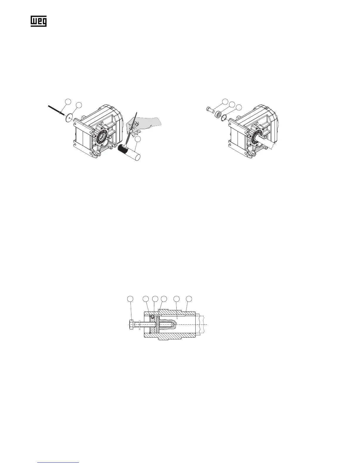
(1) Threaded rod + hex nut
(2) Thrust washer
(3) Customer-side machine shaft
(4) Retaining screw DIN6912
(5) Tension disc
(6) Circlip DIN472
Parts (4), (5) and (6) are included in the optional xing kit GMBSBSD.
Demounting:
1. Loosen the xing bolt (4). Remove the complete xing set and, if existing, the distance tube.
2. Put the pressure disc (11), jack nut (10) and circlip (6) into the hollow shaft.
3. Screw in the xing bolt (9). Through tightening of the screw you are pressing the gear off the machine shaft (3).
3 8111069
(3) Customer's shaft with tapped centre hole as per DIN332, sh.1
(6) Circlip DIN 472
(8) Hollow shaft
(9) RetainingscrewDIN933(tocustomerspecication,lengthaccordingtomachineshaftlength)
(10) Jack nut
(11) Thrust washer
Figure 2: Tightening the customer shaft Figure 3: Mounting the customer shaft using a mounting set
Figure 4: Demounting the customer shaft with or without contact shoulder
3. Before tightening the hollow-shaft gear unit onto the machine shaft, paint the surface of the machine shaft with lubrica-
ting paste (3) such as Klüber Paste 46MR401.
4. Mount the drive onto the machine shaft (4, 5). An additional distance tube is required for a customer’s shaft without
contact shoulder.
5. Implement the optionally obtainable xing set into the hollow shaft and secure the customer’s shaft axial with the
locking bolt (4). Screw tightening torque see Table 5 on page E-38.