WG20 Geared Motors | E-21
7.3.5.Installation and demounting of shrink disks
Theshrinkdiscsaresuppliedreadytoinstall.Theymustnotbetakenapartpriortotherstinstallation.Thetighten-
ing of the locking bolts without an implemented customer’s shaft can lead to a deformation of the hollow shaft.
.
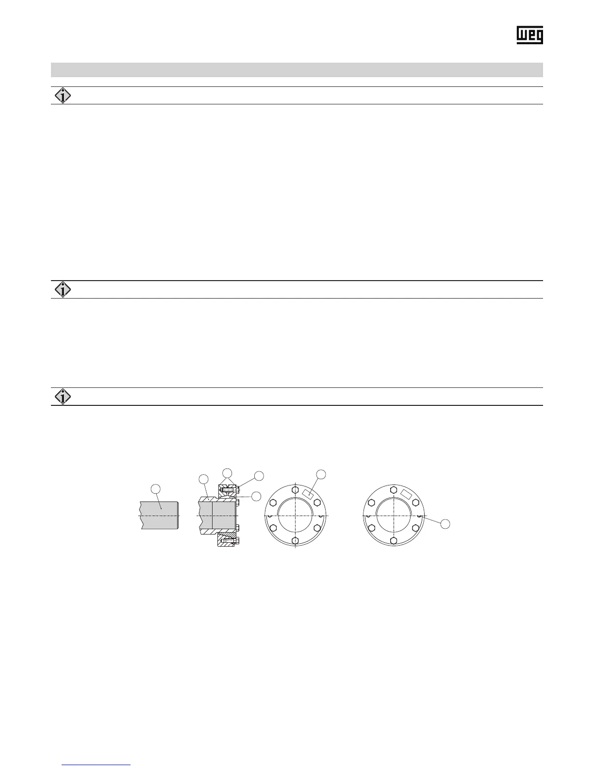
Assembling (see Figure 5):
1. Remove the possibly existing cover cap.
2. Loosen the locking bolts (3) with just a few threads. Do not screw them out completely!
3. Thoroughly degrease the entire hollow shaft boring (2, grey area). It must be ABSOLUTELY free of grease!
4. Thoroughly degrease the machine shaft (1, grey area) in the clamping area of the shrink disc. It must be ABSOLUTELY
free of grease!
5. Push the shrink disc onto the hollow shaft (2) until the outer ring of the shrink disc is ush with the hollow shaft (2). The
outer part of the hollow shaft (2) can be greased in the area where the shrink disc is tted.
6. Insert the degreased machine shaft (1) into the hollow shaft (2) so that the area of the shrink connection is fully used.
7. Slightly tighten the locking bolts (3) in sequence clockwise with several turns, so that both outer rings (5) are clamped
parallel towards each other. The number of locking bolts depends on the size of the shrink disc.
Do not tighten the locking bolts (3) „CROSSED“!
8. Tighten the locking bolts (3) with a torque key up to the indicated screwing torque (6) on the shrink disc. After the
tightening of the locking bolts (3) there has to be an even gap between the outer rings (5). If it is not the case the shrink
disc has to be mounted anew.
After installation you can sign the hollow shaft respectively the machine shaft with a marking (use a pencil) to
detect a slipping during the initial operation (under load).
1
2
4
3
6
5
1
2
3
4
5
6
7
(1) Customer-side machine shaft
(2) Hollow shaft
(3) Locking screw
(4) Inner ring
(5) Outer ring
(6) Tightening torque of the locking screws
(7) Jack nut
Demounting:
1. Undo the locking screws (3) uniformly and in sequence. Only undo each locking bolt about a quarter turn initially. Do
not remove the locking bolts completely.
2. Press the inner ring (4) off using the jack nut (7). Remove any rust beforehand that may have formed on the machine
shaft in front of the hollow shaft.
3. Remove the shrink disc from the hollow shaft (2) .
4. Step 2 only required for two-part shrink disk execution!