E-22 | WG20 Geared Motors
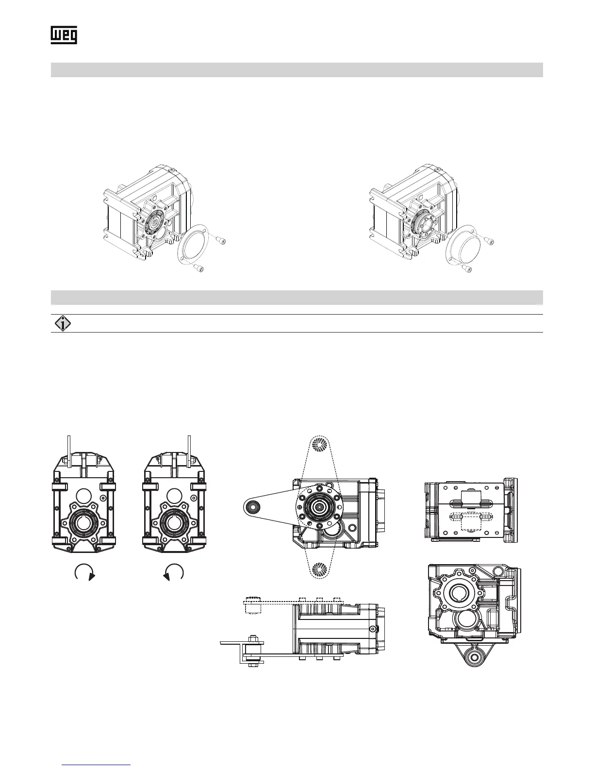
7.3.6.Installation and demounting of protection cap
7.3.7.Installation of torque arms
Before being installed, the protection caps must be inspected for any damage that might have occurred during transport.
Damaged protection caps must not be installed, since they can possibly cause abrasion. All of the xing bolts are to be
used and secured by wetting them with a thread-locking adhesive (medium strength).
Bolt tightening torque see Table 5 on page E-38.
Pay attention to the direction of rotation of the hollow shaft!
The Urelast springs in the rubber buffer set are to be loaded under compression in the main working direction of rotation!
Recommended pre-loading of the Urelast spring: 2 mm (F02, F03) or 3 mm (F04, F05, F06, F07)
R L
Clockwise Counterclockwise
Figure 6: Protection cap for hollow shaft Figure 7: Protection cap for shrink disc hollow shaft
Figure 8: Parallel shaft gear unit Figure 9:
Helical bevel gear unit K02 - K05
Figure 10:
Helical bevel gear unit K06 - K07
Possible positions of the torque arm:
K02: 90 °, 135 °, 180 °, 225 °, 270 °
K03 - K05: 90 °, 120 °, 150 °, 180 °, 210 °, 240 °, 270 °