Installation and operating instruction
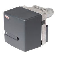
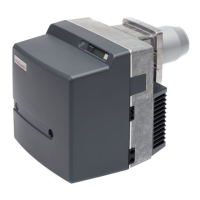
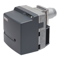
Gas burner WG10…/0-D ZM-LN
3 Product description
83300902 1/2019-02 La
14-112
3.3.4 Program sequence
The operating phases for commissioning the burner are shown on the display.
Phase Function
TEST After the power supply has been switched on the combustion manager performs a self-test.
G L At heat demand, the actuators for the air damper and the gas butterfly valve drive to the reference
point.
1 The combustion manager monitors for extraneous light.
2 The air damper actuators drives to pre-purge (operating point P9). The gas butterfly valve actuator
drives to ignition position (operating point P0).
3 Pre-purge is initiated. The air pressure switch reacts.
4 Pre-purge. The remaining pre-purge time is displayed.
5 The air damper actuator drives to ignition position (operating point P0).
6 Gas valve1 opens. The gas pressure switch reacts. Ignition starts.
7 Gas valve2 opens. The fuel is released. The safety time begins. The display shows symbol .
8 Flame stabilisation.
9 The actuators for the air damper and gas butterfly valve drive to partial load.
10 The burner is in operation. Load control is activated.
11 If heat demand is no longer available, the actuators for air damper and gas butterfly valve drive to par-
tial load.
Valve proving starts.
1. Test phase (function sequence for valve proving valve1):
Valve 1 closes,
valve 2 closes after a delay,
the gas escapes and the pressure between valve 1 and valve 2 reduces.
12 Test time valve1.
13 2. Test phase (function sequence for valve proving valve2):
Valve 1 opens, valve 2 remains closed,
pressure between valve1 and valve2 increases,
valve 1 closes again.
14 Test time valve2.
15 Following the post-purge phase the burner motor switches off. The air damper and gas butterfly valve
actuators close.
OFF Standby, no heat demand.
 Loading...