Installation and operating instruction
Gas burner WG10…/0-D ZM-LN
3 Product description
83300902 1/2019-02 La
16-112
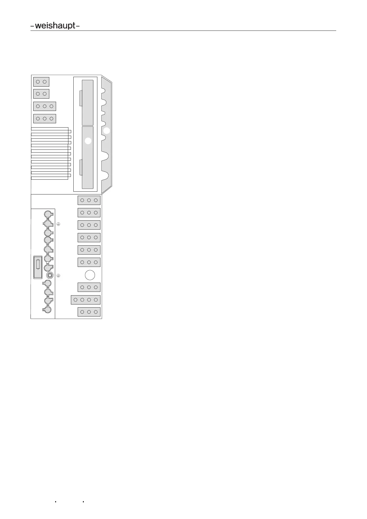
3.3.5 Inputs and outputs
Observe wiring diagram supplied.
-weishaupt-
13
3
N
7
3
C
4
1
6
5
14
L
N
T1
T2
S3
B4
B5
T6
T7
T8
G L/A AM FU NA P
TWI
8
11
15
12
X6
X7
F7
1
2
TWI TWI interface (VisionBox, accessory)
P O2 sensor (accessory)
NA not used
FC not used
AM Operating panel
L/A Air damper actuator
G Gas butterfly valve actuator
1 Slot for analogue module EM3/3 or fieldbus module EM3/2
2 W-FM cover
1 External valve LPG
3C Burner motor for continuous running fan
3N Burner motor
4 Ignition unit
5 Multifunction assembly
6 not used
7 Bridging plug No. 7
8 Gas meter (impulse generator)
11 Air pressure switch / air pressure switch for ducted air intake
(LDW2)
12 Low gas pressure switch/valve proving gas pressure switch
13 Ionisation
14 Remote reset or low gas pressure switch (optional)
15 Bridging plug No. 15 or high gas pressure switch
X6 7 pole connection plug
X7 4 pole connection plug
F7 Internal unit fuse (T6.3H, IEC 127-2/5)
 Loading...